
Fault detection method and system for multi-branch PON (Passive Optical Network)

A passive optical network, fault detection technology, applied in transmission monitoring/testing/fault measurement systems, selection devices for multiplexing systems, transmission systems, etc. The problems of increasing the cost of the detection system, etc., achieve the effect of low detection cost, easy accurate identification, and convenient detection.

Inactive Publication Date: 2011-06-22
ZTE CORP
View PDF4 Cites 49 Cited by
  • Summary
  • Abstract
  • Description
  • Claims
  • Application Information

AI Technical Summary

Problems solved by technology

Since the echo signals of each branch in this way will not be superimposed, it can provide an effective means of fault detection for a multi-branch network, but the number of OTDR instruments in the system will increase sharply, and the cost of the fault detection system will also increase significantly, and each ONU Branch detection information needs to be transmitted to the network management system at the OLT side. When an optical path branch fails, additional lines need to be added to transmit detection information, making the fault detection system more complicated

Method used


Image

  • Fault detection method and system for multi-branch PON (Passive Optical Network)
  • Fault detection method and system for multi-branch PON (Passive Optical Network)
  • Fault detection method and system for multi-branch PON (Passive Optical Network)

Examples


no. 1 example

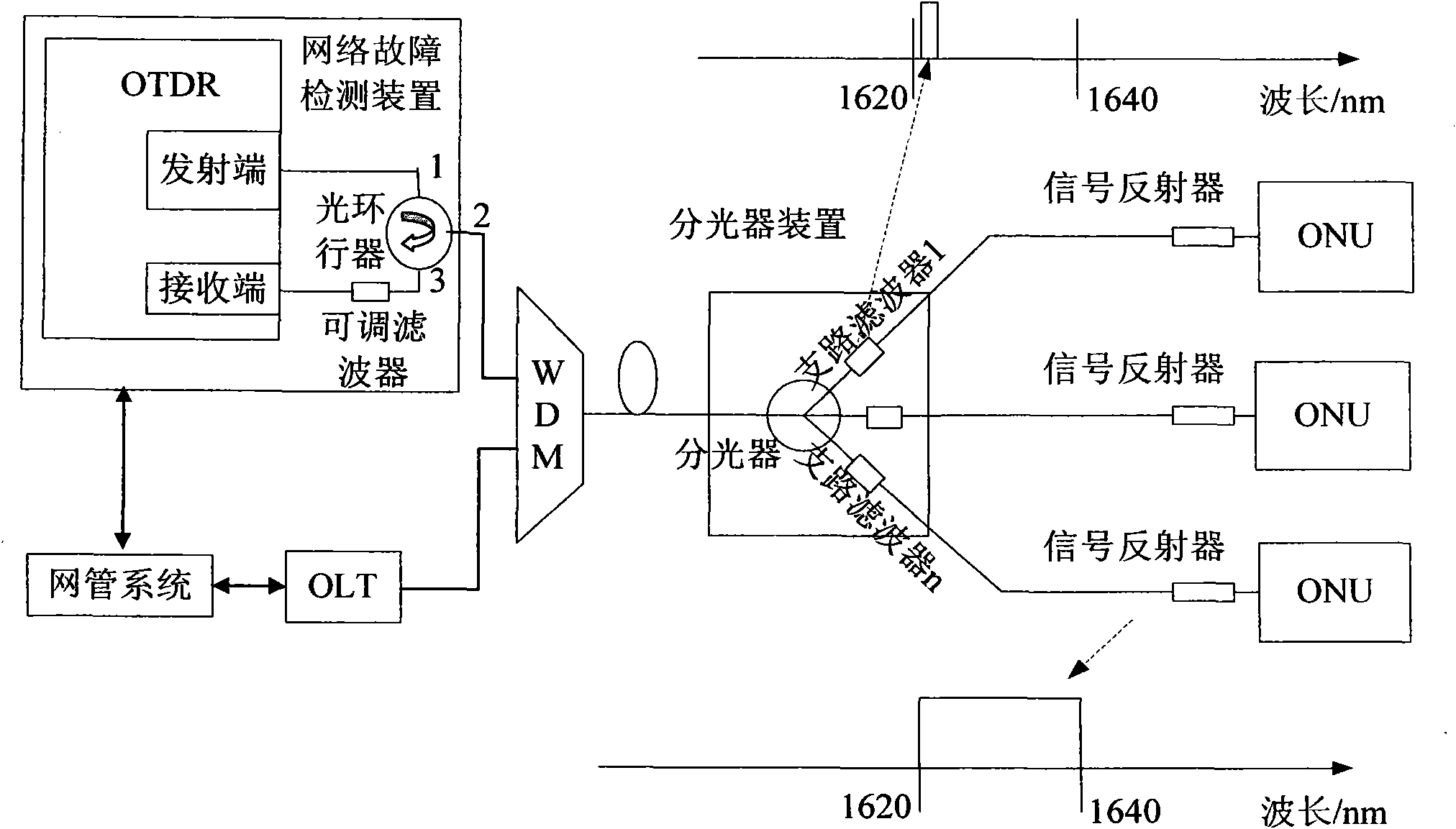
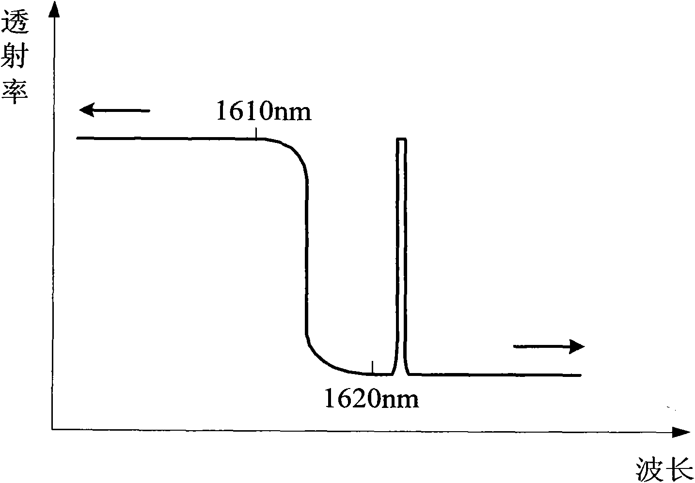
[0046] The detection light source of this embodiment adopts broad-spectrum light, and the spectrum of the broad-spectrum light includes the detection center wavelength of each ONU branch branch filter, and the OTDR receiving end is equipped with an adjustable filter accordingly. The detection light is output through the optical circulator and coupled into the PON through the wavelength division multiplexer. By configuring different branch filters for each ONU branch in the optical splitting device, the wavelength of the detection light in the ONU branch is different, and the detection The light propagates along each ONU branch, and its Rayleigh scattered light and Fresnel reflected light signals propagate backward and are received by the OTDR through an adjustable filter. According to the detection requirements of the OLT, adjust the central wavelength of the adjustable filter to correspond to the detection central wavelength of the branch filter of the ONU branch to be tested,...

no. 2 example

[0072] The detection light source of the OTDR in this embodiment adopts an adjustable narrow-band light source such as an adjustable laser, and an adjustable filter is set at this time. During detection, the wavelength of the emitted detection light is adjusted to the detection center wavelength of the branch filter of the ONU branch to be tested, so that the detection light can only be transmitted in the specific ONU branch, so that one of the multi-branch optical paths can be selected for detection. detection.

[0073] Figure 6 It is a structural diagram of the fault detection system of this embodiment, which is similar to the first embodiment, and also includes a network fault detection device, a wavelength division multiplexer, an optical splitter, and a signal reflector. Wherein, the optical splitting device and the signal reflector are the same as those in the first embodiment, and will not be repeated here. In addition to the coupling function, the wavelength division...


PUM

PropertyMeasurementUnit
Wavelengthaaaaaaaaaa

Abstract

The invention discloses a fault detection method and system for a multi-branch PON (Passive Optical Network), comprising a network fault detection device, a WDM (Wavelength Division Multiplexer) and a light splitting device. The network fault detection device is arranged at one OLT (Optical Line Terminal) side and used for emitting detection light and transmitting the detection light to the WDM; a detection light echo signal, the wavelength of which is the central detection wavelength of branch filters of an ONU (Optical Network Unit) to be detected, is received for fault analysis; the WDM is arranged at the OLT side and used for coupling the detection light into the multi-branch PON and transmitting the detection light to the light splitting device through a trunk fiber; the light splitting device comprises a light splitter and a plurality of branch filters respectively mounted on all ONU branches, the central detection wavelengths of all branch filters in the same light splitting device are different from one another, and the central detection wavelength of a certain branch filter is the wavelength of the detection light capable of being filtered by the branch filter. The fault detection method and system provided by the invention are simple and low in cost, and effectively realize the fault detection of the multi-branch PON.

Description

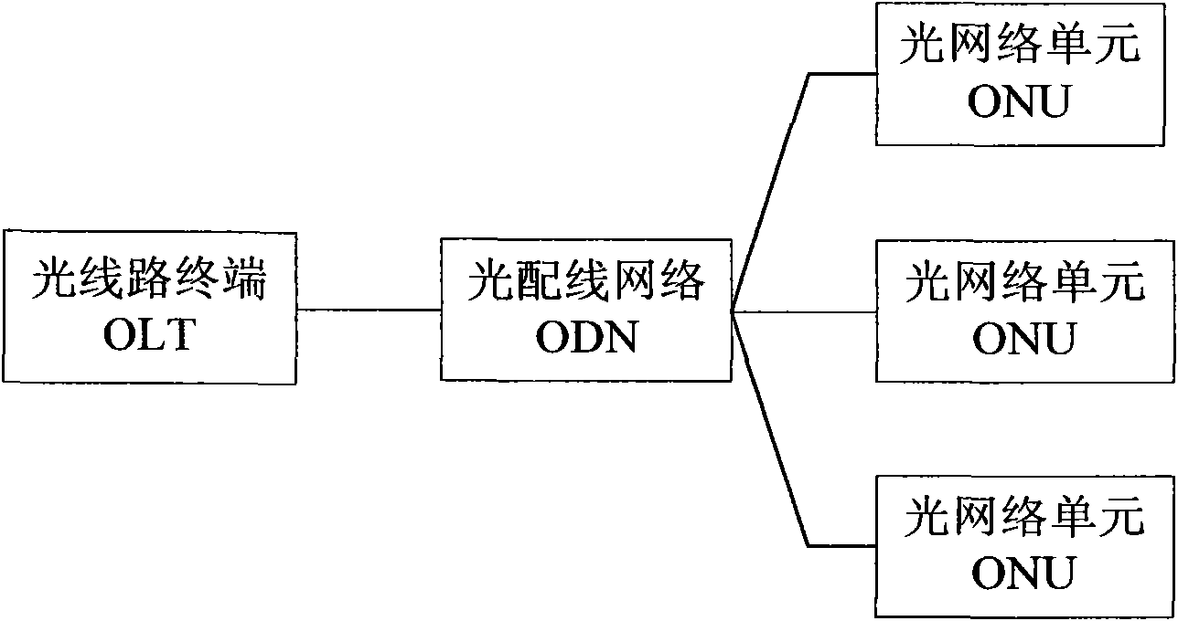
technical field [0001] The invention relates to a passive optical network fault detection technology in the field of optical access networks, in particular to a multi-branch passive optical network fault detection method and system. Background technique [0002] With the rapid growth of today's communication services, a Passive Optical Network (PON) capable of providing higher bandwidth has been rapidly developed. PON is a point-to-multipoint network, its structure is as follows figure 1 As shown, the system is mainly composed of an optical line terminal (OLT) at the central office, an optical network unit (ONU) at the user end, and an optical distribution network (ODN). Compared with the point-to-point topology, the point-to-multipoint structure of PON can greatly reduce the cost of optical fibers. However, this multi-branch PON topology poses a great challenge to the network fault detection technology. [0003] At present, the fault detection of the network system mainly...

Claims


Application Information

Patent Timeline
IPC IPC(8): H04B10/08H04Q11/00H04B10/03H04B10/07
Inventor 朱松林苏婕李长垒何子安高树钦孙畅
Owner ZTE CORP
Learn More