LED drive circuit

A circuit and control circuit technology, which is applied in the field of high power factor non-isolated LED drive circuits, can solve the problems of reducing circuit efficiency and achieve low cost, meet power factor and harmonic requirements, and high reliability.

Inactive Publication Date: 2011-06-22
BCD SEMICON MFG
View PDF3 Cites 33 Cited by
  • Summary
  • Abstract
  • Description
  • Claims
  • Application Information

AI Technical Summary

Problems solved by technology

However, some LED lighting applications do not require isolation, and the use of an i

Method used


Image

  • LED drive circuit
  • LED drive circuit
  • LED drive circuit

Examples


Example Embodiment

[0027] In order to make the above objects, features and advantages of the present invention more comprehensible, the present invention will be further described in detail below in conjunction with the accompanying drawings and specific embodiments.

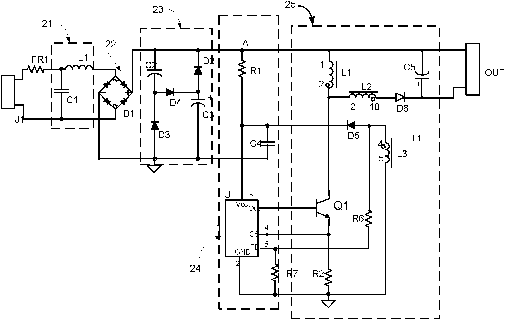
[0028] see figure 2 , shows the drive circuit structure of the present invention, the drive circuit includes an input filter circuit 21 , a rectifier bridge 22 , a power factor correction circuit 23 , a control circuit 14 and a constant current output circuit 25 .

[0029] The positive end of the AC input is connected to the filter circuit 21 through the fuse F1. The filter circuit 21 includes an inductor L1 and a capacitor C1. One end of the inductor L1 is connected to the fuse F1, and the other end is connected to the input end of the rectifier bridge 22; one end of the capacitor C1 is connected to the inductor L1 and the fuse F1. common end, the other end is connected to the common end of the AC input negative end and the rect...


PUM


Abstract

The invention relates to an LED drive circuit, comprising a rectifier bridge, a power factor correcting circuit, a control circuit and a constant current output circuit, wherein the output end of the rectifier bridge is connected with the power factor correcting circuit which is a flow-by-flow power factor correcting circuit; the control circuit comprises a controller, an Out end of which is connected with a control end of a switch element; a first conducting end of the switch element is connected with a cathode of a second diode through a first inductor, and a second conducting end of the switch element is connected with an CS end of the controller; a corresponding end of the first inductor is connected with an anode cathode of a sixth diode through a second inductor, and a cathode of the sixth diode is connected with an output negative end; a non-corresponding end of the first inductor is connected with an output positive end. The invention meets the requirements for power factor and harmonic wave and can output constant current, and has the advantages of high efficiency, high dependability, small volume and low cost; furthermore, the output capacitor can be a small capacitor and even is unnecessary.

Description

technical field [0001] The invention relates to the field of LED drive circuits, in particular to a non-isolated LED drive circuit with high power factor. Background technique [0002] As an emerging industrial technology, LED lighting is constantly developing a wider range of applications. The LED drive circuit is a key link in LED technology, and a drive circuit based on a flyback topology is usually used at present. [0003] figure 1 It is the system schematic diagram of the existing drive circuit. The drive circuit includes an input rectification filter circuit 11, a switch control circuit 12, an isolation transformer 13 and an output rectification filter circuit 14, a transformer consisting of a transformer primary winding 105, a transformer secondary winding 106 and a transformer auxiliary winding 107, coupled to the transformer primary The first control circuit 110 of the winding 106 , the first control circuit 110 includes a drive circuit 111 and a feedback contro...

Claims


Application Information

Patent Timeline
IPC IPC(8): H05B37/02
Inventor 朱士海
Owner BCD SEMICON MFG
Why Eureka
Try Eureka