Antenna evaluation device and method
A technology for measuring devices and antennas, applied in the direction of measuring devices, antennas, antenna radiation patterns, etc.
- Summary
- Abstract
- Description
- Claims
- Application Information
AI Technical Summary
Problems solved by technology
Method used
Image

Examples
no. 1 Embodiment approach
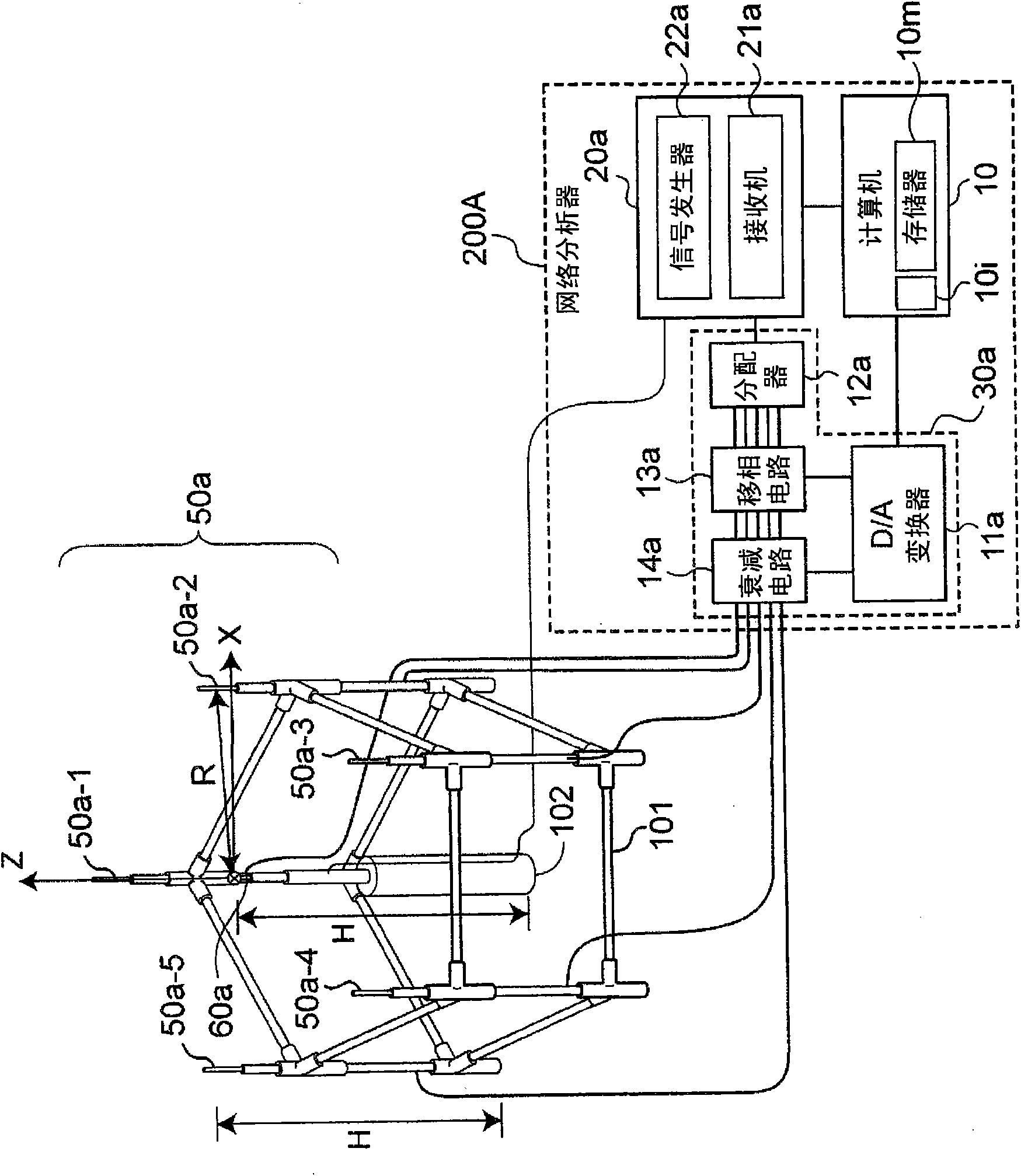
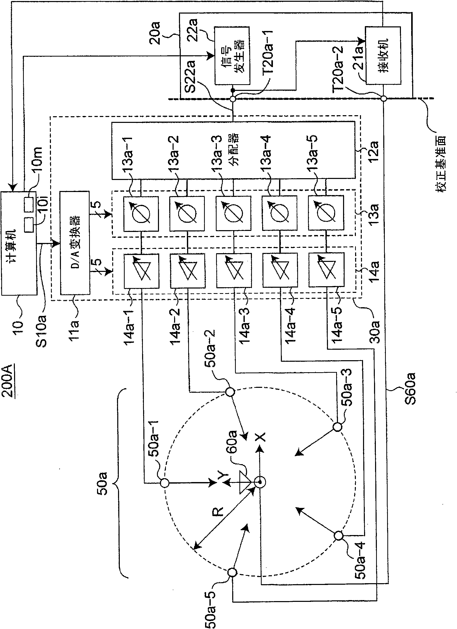
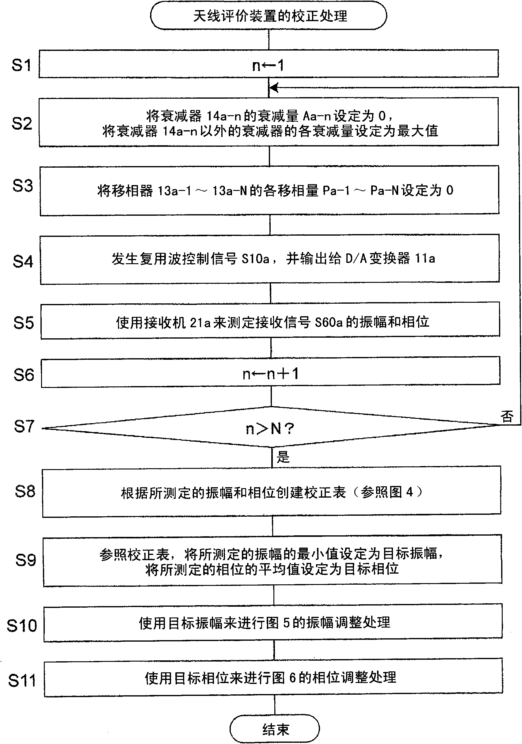
[0066] As will be described later in detail, the antenna evaluation device according to this embodiment is characterized in that the computer 10 controls the transmission circuit 30a such that the scatterer antennas 50a-n (n=1, 2, . . . , N, In the present embodiment, N is 5) radiate radio waves individually, and perform calibration as follows: The transmission circuit 30a is controlled based on the radio waves radiated independently from the scatterer antennas 50a-n so that the received signals respectively measured by the calibration receiving antennas 60a The amplitude of S60a coincides with the same target amplitude and the phases of the received signals measured respectively are consistent with the same target phase, and the reference attenuation control voltage VAa-n and the reference phase shift of the transmitting circuit 30a of each of the above-mentioned scatterer antennas 50a-n Quantity control voltage VPa-n is stored in memory 10m. It is also characterized in that,...
no. 2 Embodiment approach
[0090] Receiving antennas 60a and 60b are half-wavelength dipole antennas that receive vertically polarized radio waves, respectively. And, the receiving antennas 60a and 60b are longitudinally installed on the apex portion of the receiving antenna support stand 102, so that the feeding points are respectively set at the coordinate position (0, λ / 4, 0) and the coordinate position (0, -λ / 4) of the XYZ coordinate system. , 0), and receive electric waves of vertically polarized waves. Here, λ is the wavelength of radio waves radiated from the scatterer antennas 50a-1 to 50a-5. The receiver 21a multiplexes radio waves radiated from the scatterer antennas 50a-1 to 50a-5 via the receiving antenna 60a or a first evaluation receiving antenna (not shown) provided instead of the receiving antenna 60a and an attenuator 84. The wave is received as received signal S60a. The attenuator 84 is inserted between the receiving antenna 60a or the first evaluation receiving antenna and the recei...
no. 3 Embodiment approach
[0103] The scatterer antennas 50b-n are longitudinally installed on the scatterer antenna support table 101, so that the feeding points of the scatterer antennas 50b-n are arranged at a distance of λ / 2 from the feeding points of the scatterer antennas 50a-n in a direction away from the origin position, and emit horizontally polarized radio waves. For example, the coordinate positions of the feeding points of the scatterer antennas 50 a - 1 and 50 b - 1 in the XYZ coordinate system are (0, R, 0) and (0, R+λ / 2, 0), respectively. In addition, the longitudinal directions of the scatterer antennas 50b-n are set parallel to the tangent of the circle centered on the origin.
[0104] The computer 10 generates a multiplexed wave control signal S10a and outputs it to the D / A converter 11a when performing calibration of the antenna evaluation device and evaluation of the receiving antenna for evaluation, as in the first embodiment. In addition, when the computer 10 performs the calibrat...
PUM
 Abstract
Description
Claims
Application Information
PatSnap Eureka turns technology decisions into work you can execute. Powered by our Innovation Knowledge Graph, it runs expert workflows across engineering, life sciences, materials and intellectual property. Get your review-ready output in minutes.


