Hand-guided power tool having a torque coupling

A technology for torque clutches and power tools, applied in power tools, manufacturing tools, wrenches, etc., can solve problems such as large adjustment force and impaired comfort, and achieve the effect of simple cost, simple and compact structure

Inactive Publication Date: 2011-06-29
ROBERT BOSCH GMBH
View PDF6 Cites 10 Cited by
  • Summary
  • Abstract
  • Description
  • Claims
  • Application Information

AI Technical Summary

Problems solved by technology

However, such a spring element requires high adjustment forces when adjusting the maximum permissible torque, which impairs the comfort when using the power tool

Method used


Image

  • Hand-guided power tool having a torque coupling
  • Hand-guided power tool having a torque coupling
  • Hand-guided power tool having a torque coupling

Examples


Embodiment Construction

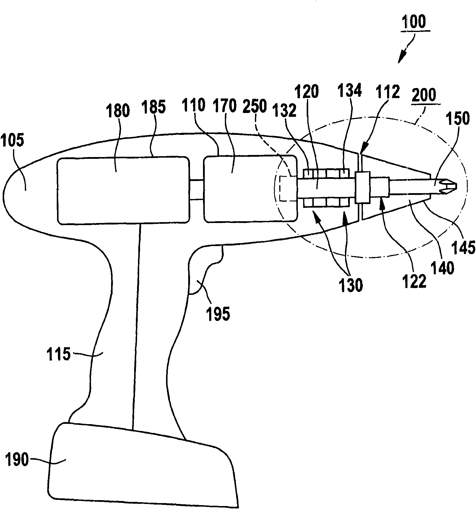
[0029] figure 1 A hand-held power tool 100 is shown having a housing 105 with a handle 115 . According to one embodiment, electric tool 100 can be mechanically and electrically connected to battery pack 190 for power supply independent of the mains. exist figure 1 Among them, the power tool 100 is, for example, designed as a cordless screwdriver drill. However, it should be pointed out that the invention is not restricted to cordless drills, but rather can be used in various electric tools, in particular powered by rechargeable batteries, in which the tool is turned, for example in Cordless screwdrivers, cordless impact drills, etc.

[0030] An electric drive motor 180 powered by a battery pack 190 and a transmission 170 are arranged in the housing 105 . The driving motor 180 is connected to the driving shaft 120 via the transmission mechanism 170 . In the drawing, drive motor 180 is arranged in motor housing 185 and transmission 170 is arranged in transmission housing 11...


PUM


Abstract

The invention relates to a hand-guided power tool (100) having a torque coupling. The torque coupling (250) has a planetary gear (170) disposed in a gearbox (110) for transmitting a torque, generated by a drive motor (180), to a drive shaft (120). The planetary gear (170) has at least one ring gear (206), axially displaceable in the gearbox (110), for releasing the torque coupling (250).

Description

technical field [0001] The invention relates to a hand-held electric tool with a torque clutch having a planetary gear arranged in a gear housing for transmitting a torque generated by a drive motor to a drive shaft. Background technique [0002] Hand-held power tools of this type are known from the prior art, in which the planetary gear has a ring gear provided with a retaining body, which together with an associated axially displaceable pressure body forms a torque coupling , to assign a maximum permissible torque to the torque clutch, which torque can be adjusted via the actuator. In this case, the pressure body and thus the blocking element arranged thereon are pressed by the spring element with a predetermined pressing force against the end face of the ring gear, on which the stop body is formed. During operation of the power tool, the blocking element blocks the blocking body until the maximum permissible torque is reached, thereby preventing the ring gear from rotati...

Claims


Application Information

Patent Timeline
Patent Type & Authority Applications(China)
IPC IPC(8): B25F5/00B25B21/00B23B45/02
CPCB25F5/001B25B23/141B25B23/14
Inventor H·勒姆T·赫尔
Owner ROBERT BOSCH GMBH
Why Eureka
Try Eureka