Dual submodule for a modular multilevel converter and modular multilevel converter including the same

a multi-level converter and multi-level technology, applied in the direction of power conversion systems, climate sustainability, conversion with reversal, etc., can solve the problems of increasing the complexity of the circuit, and increasing the cost of the converter as a whole, so as to achieve low line loss in operation, the effect of being convenient to use and easy to us

Active Publication Date: 2019-02-14
GE ENERGY POWER CONVERSION TECH
View PDF6 Cites 9 Cited by
  • Summary
  • Abstract
  • Description
  • Claims
  • Application Information

AI Technical Summary

Benefits of technology

[0013]The invention therefore aims to provide a submodule for use in a modular multilevel converter with a similar voltage and current characteristics as half-bridge-based submodules, and that is relatively inexpensive and uncomplicated, and in particular requiring a small number of power semiconductor switches, and having low line losses in operation. In an embodiment, the submodule can be used with a mechanical basic structure consisting of other existing submodule types.

Problems solved by technology

However, this is achieved with a higher number of power semiconductor switches and thus the increased circuit complexity and increased costs of the converter as a whole.
In addition, in the case of such full bridge-based submodules, two switches are always current-conductive, as a result of which the line losses are increased significantly compared to half-bridge-based submodules.
For applications in the medium and high-voltage range, such line losses can be unacceptable.
To this extent, relatively high limit load-integral requirements must also be imposed on the diodes used.
However, this increases the complexity and costs of the submodule circuit and its operation.
The use of full bridges results in a relatively high number of power semiconductor switches and increased line losses in operation.
In the case of dual submodules, which cause a parallel connection of the two intermediate circuit capacitors due to certain switching states, different voltages of the capacitors can lead to partial large compensation currents and correspondingly higher losses within the submodules.

Method used


Image

  • Dual submodule for a modular multilevel converter and modular multilevel converter including the same
  • Dual submodule for a modular multilevel converter and modular multilevel converter including the same
  • Dual submodule for a modular multilevel converter and modular multilevel converter including the same

Examples


Embodiment Construction

[0037]Reference will now be made to the embodiments of the invention, which are illustrated in the drawings. It should be understood that the embodiments illustrated in the drawings are merely exemplary and do not limit the invention as such. Rather, the embodiments are merely intended to explain possible embodiments and enable the person skilled in the art to execute the invention. It must also be understood that, in an effort to provide a concise description of possible embodiments, not all of the details covered by the scope of the invention can be given.

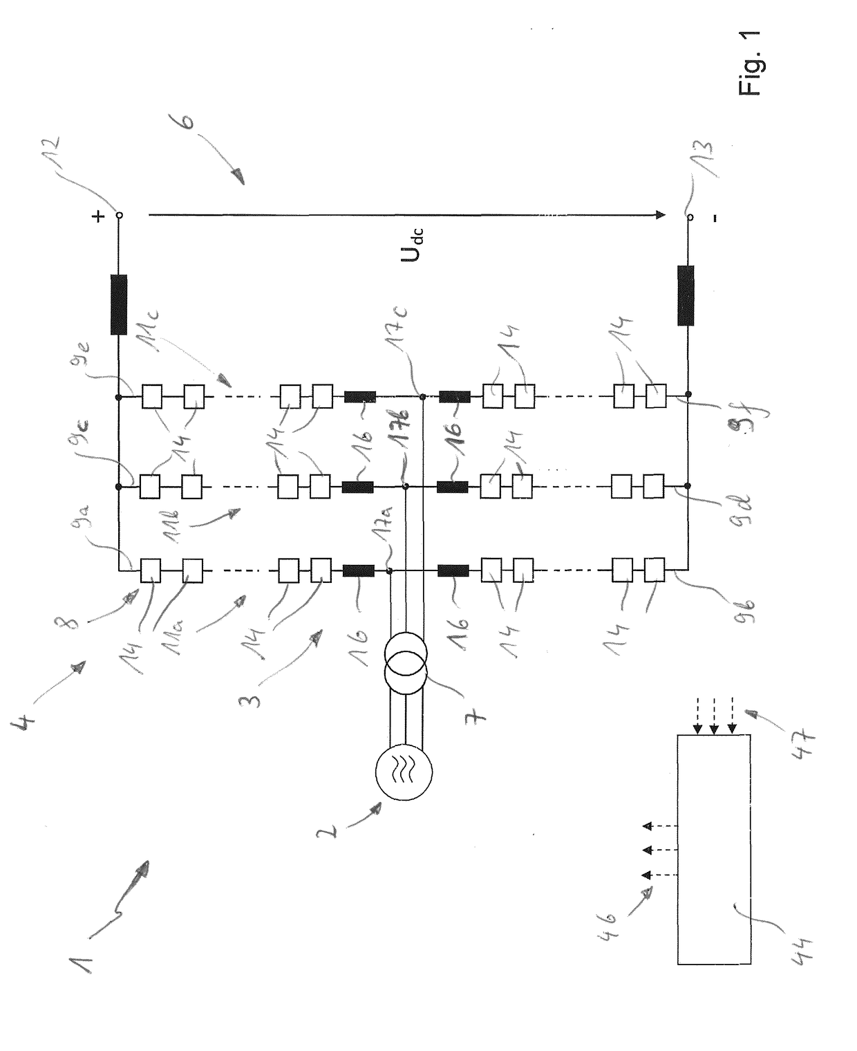
[0038]FIG. 1 shows a highly simplified illustration of system 1 that can represent e.g. a high-voltage or medium-voltage DC distribution system for electrical energy transmission at high or medium DC voltages. Such a system could be used, for example, for coupling DC voltage applications to alternating current networks, e.g. photovoltaic or busbar systems with DC voltage or DC voltage networks. In addition, such a system can also...


PUM


Abstract

A dual submodule is created for a modular multilevel converter, whereby the dual submodule has two interconnected submodules, whereby each submodule has an asymmetrical half-bridge circuit with two parallel bridge branches, which are connected between a first and a second terminal connection of the submodule, whereby each bridge branch is formed from a series circuit of a power semiconductor switch, and a diode, whereby the power semiconductor switch is allocated to an antiparallel free-wheeling diode, and has a capacitor, which is connected in parallel with the asymmetrical half-bridge circuit between the first and the second terminal connections of the module. The submodules are connected to each other via their AC terminals to form the dual submodule. Further, a modular multilevel converter is created, comprising a number of such dual submodules in each of its converter branches.

Description

[0001]This invention relates to a dual submodule for a modular multilevel converter and a modular multilevel converter with a series connection of such dual submodules.BACKGROUND OF THE INVENTION[0002]Converters for converting direct current to alternating current and vice versa are used for many applications, e.g. for coupling electrical networks with variable speed drives for energy exchange between two electrical networks, etc. For this purpose, converters are known in various circuit topologies and configurations. For smaller and medium-sized powers, conventional two-phase converters are known which offer simple and robust solutions and are widely used.[0003]With the continuous development of power semiconductor switches and the application possibilities of power electronics, ever newer converter topologies for ever higher power and voltage ranges are being sought and developed. In the medium and high-voltage range, the so-called multilevel converters are frequently used to gene...

Claims


Application Information

Patent Timeline
Patent Type & Authority Applications(United States)
IPC IPC(8): H02M7/483H02M1/32H02M7/66
CPCH02M7/483H02M1/32H02M7/66H02M2007/4835H02M2001/007H02M2001/0054H02M7/4835H02M1/0085Y02B70/10H02M1/0054
Inventor GESKE, MARTINJANNING, JOERG
Owner GE ENERGY POWER CONVERSION TECH
Why Eureka
Try Eureka