

Gyroscopic control system for tyre crane
A technology of tire crane and control system, applied in cranes, load hanging components, transportation and packaging, etc., can solve the problems of unstable operation of the slewing controller, complex control system, unsatisfactory effect, etc., to reduce the hidden danger of power supply, High control precision and the effect of increasing safety and stability
Inactive Publication Date: 2011-06-29
WUHAN UNIV OF TECH
View PDF4 Cites 12 Cited by
- Summary
- Abstract
- Description
- Claims
- Application Information
AI Technical Summary
Problems solved by technology
Method used
View moreImage
Smart ImageViewing Examples

Examples
Embodiment Construction
Login to View More PUM
 Abstract
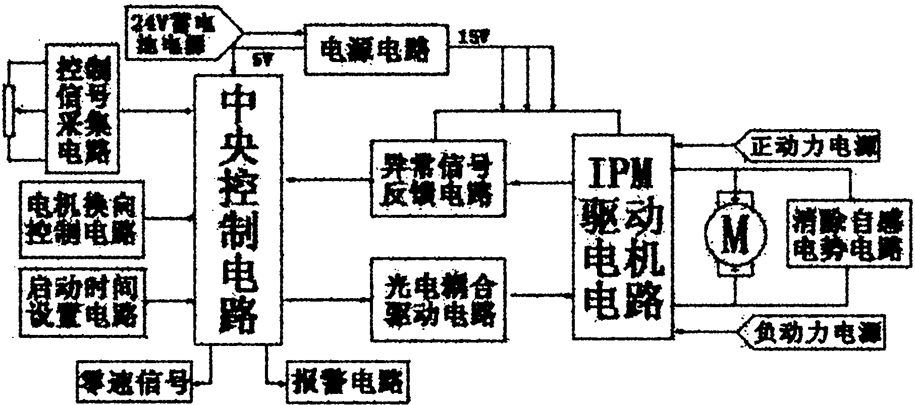
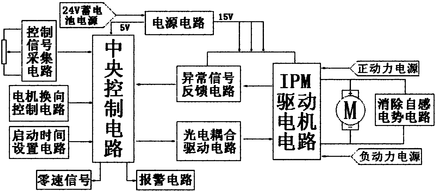
The invention relates to a gyroscopic control system for a tyre crane. The system is provided with a control circuit which is formed by a power supply circuit, a control signal collection circuit, a motor commutation control circuit, a start time setting circuit, a central control circuit, an optoelectronic coupling drive circuit, an intelligent power module (IPM) drive motor circuit, an abnormal signal feedback circuit, an alarm circuit and a self-induction potential elimination circuit, wherein the control signal collection circuit, the motor commutation control circuit, the start time setting circuit and the alarm circuit are connected with the central control circuit through leads respectively; the self-induction potential elimination circuit is connected with the IPM drive motor circuit; and the central control circuit and the IPM drive motor circuit are connected with each other through the optoelectronic coupling drive circuit and the abnormal signal feedback circuit. The gyroscopic control system has the advantages of strong practicality, simple and reasonable structure, small volume, lower cost, high safety and the like, can control the gyroscopic system to work quickly and smoothly and is beneficial to popularization and application.
Description
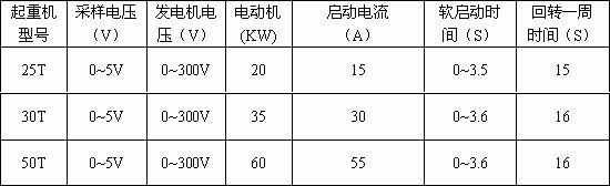
Wheel Crane Slewing Control System technical field The invention relates to the field of motor speed regulation control of a tire jib crane, in particular to a slewing control system of a tire crane. Background technique The tire jib crane is a common loading and unloading machine for port terminals and various construction projects. It can travel long distances, flexibly change the working site, and has good mobility. Its working characteristics are cyclic, repetitive, and intermittent operations, frequently lifting several tons to dozens of tons of goods, and moving the goods to the destination position through the operating mechanism, slewing mechanism or luffing mechanism. Due to the large load changes, especially the high timeliness of the port terminal, it is required that the tire crane can be started and braked in a short period of time, which requires that the slewing mechanism of the crane can run quickly and smoothly. At present, in the field of slewing control...
Claims
Login to View More Application Information
Patent Timeline
 IPC IPC(8): B66C13/22B66C23/84
Inventor胡吉全唐静陈永兴
OwnerWUHAN UNIV OF TECH