Oil distributing valve of hydraulic impactor

A technology of hydraulic impactor and oil distribution valve, which is applied in the direction of fluid pressure actuator, servo motor assembly, mechanical equipment, etc., and can solve the problem of large volume and mass of the valve core, large fuel consumption and leakage, and slow reversing speed and other problems, to achieve the effect of small volume and mass of the spool, fast reversing speed, and reduced mass of the spool

Active Publication Date: 2013-01-09
SUNWARD INTELLIGENT EQUIP CO LTD
View PDF9 Cites 0 Cited by
  • Summary
  • Abstract
  • Description
  • Claims
  • Application Information

AI Technical Summary

Problems solved by technology

The commonly used slide valve and cylinder valve are complex in technology, and the volume and mass of the valve core are relatively large, so that the reversing speed is relatively slow and the energy consumption is large; while the sleeve valve is good in technology, its oil consumption and leakage but larger

Method used


Image

  • Oil distributing valve of hydraulic impactor
  • Oil distributing valve of hydraulic impactor

Examples


Embodiment Construction

[0016] The present invention will be further described below with reference to the drawings and specific embodiments.

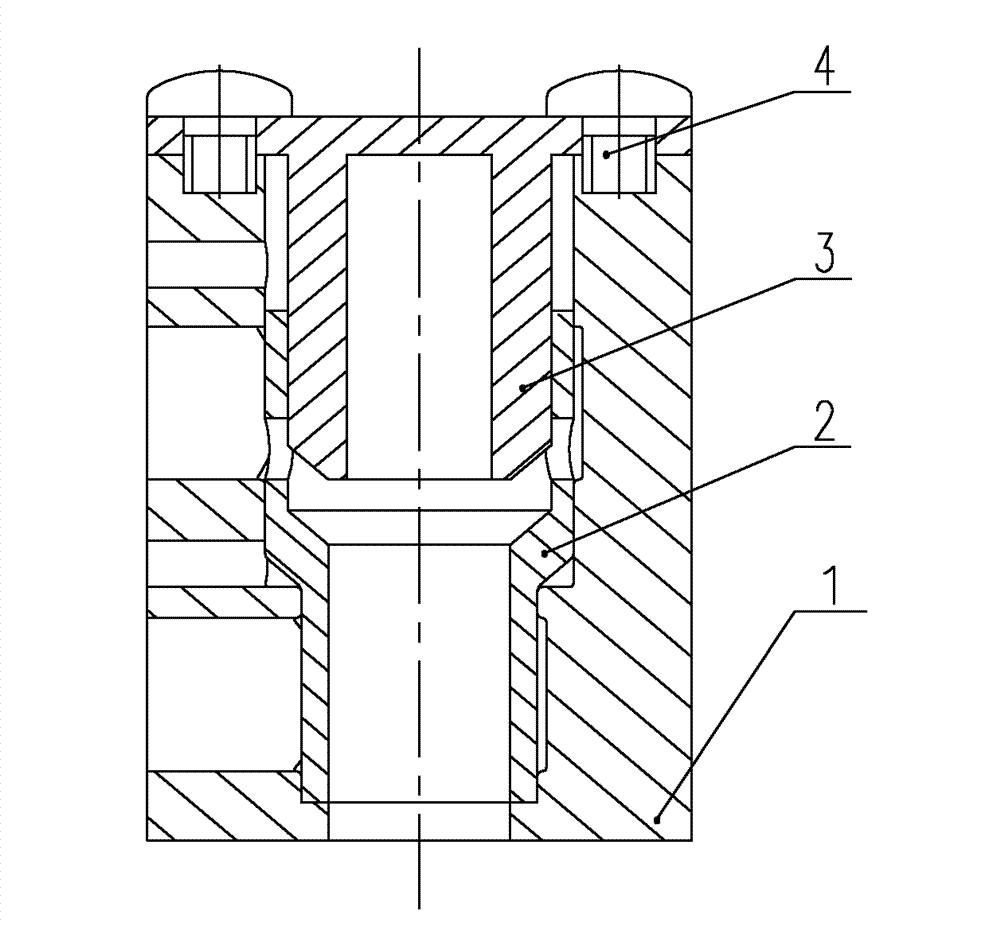
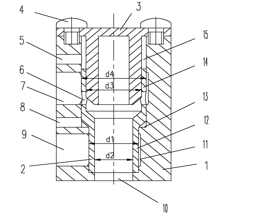
[0017] See figure 1 with figure 2 The valve cavity of the valve body 1 is composed of a rear cavity 15 with a larger diameter and a front cavity 11 with a smaller diameter. The front cavity 11 and the rear cavity 5 form a stepped surface 13, and the valve cavity of the valve body 1 is provided with energy Axial sliding spool 2. The spool 2 is hollow and consists of a rear end 14 adapted to the size of the rear cavity 15 and a front end 12 adapted to the size of the front cavity 11. One end of the valve cover 3 is slidably fitted on the rear end of the spool 2 In 14, the other end is fixed on the valve body 1 by the connecting screw 4. The valve body 1 is provided with a first high pressure oil port 5 communicating with the rodless cavity of the rear cavity 15, and an oil return communicating with the rod cavity of the rear cavity 15. Port 7, the feedback oil p...


PUM


Abstract

The invention discloses an oil distributing valve of a hydraulic impactor. A valve cavity of a valve body (1) consists of a back cavity (15) with a larger diameter and a front cavity (11) with a smaller diameter; a valve core (2) capable of sliding axially is arranged in the valve cavity of the valve body (1); the valve body (1) is provided with a first high-pressure oil opening (5), an oil return opening (7), a feedback oil opening (8), a second high-pressure oil opening (9) and a cylinder body back cavity interface (10); when the valve core (2) is far away from the cylinder body back cavityinterface (10), the oil return opening (7) and the cylinder body back cavity interface (10) are cut off by the valve core (2), and the second high-pressure oil opening (9) is communicated with the cylinder body back cavity interface (10) by the valve core (2); and when the valve core (2) is abutted on the cylinder body back cavity interface (10), the oil return opening (7) is communicated with the cylinder body back cavity interface (10) by the valve core (2), and the second high-pressure oil opening (9) and the cylinder body back cavity interface (10) are cut off by the valve core (2). The oil distributing valve of the hydraulic impactor is easy to manufacture, and is compact in structure, small in valve core volume and mass, high in reversing speed, and low in energy consumption.

Description

Technical field [0001] The invention relates to an oil distribution valve, in particular to a hydraulic impactor oil distribution valve. Background technique [0002] Hydraulic impactors are widely used in mining, metallurgy, construction, machining and other fields, for blast hole drilling, object crushing, etc. The oil distribution valve is the core component of the hydraulic impactor, which has a great influence on the performance of the impactor. The spool valve and cylinder valve commonly used at present have complex processes, and the spool volume and mass are relatively large, so that the reversing speed is relatively slow and the energy consumption is large; while the sleeve valve has good manufacturability, but its fuel consumption and leakage But larger. Summary of the invention [0003] The technical problem to be solved by the present invention is to provide a hydraulic impactor oil distribution valve which is easy to manufacture, compact in structure, small in valve...

Claims


Application Information

Patent Timeline
Patent Type & Authority Patents(China)
IPC IPC(8): F15B13/02
Inventor 舒敏飞何清华赵宏强
Owner SUNWARD INTELLIGENT EQUIP CO LTD
Why Eureka
Try Eureka