
Pressure-sharing cavity air thrust bearing

A thrust bearing and pressure cavity technology, applied in the direction of bearings, shafts and bearings, mechanical equipment, etc., can solve the problems of limited accuracy, rareness, and complicated processing technology of porous materials for air-bearing bearings, so as to suppress the bearing vibration phenomenon, Hazard reduction effect

Active Publication Date: 2011-06-29
SHANGHAI MICRO ELECTRONICS EQUIP (GRP) CO LTD
View PDF3 Cites 6 Cited by
  • Summary
  • Abstract
  • Description
  • Claims
  • Application Information

AI Technical Summary

Problems solved by technology

However, the processing technology of porous materials is complex, and the manufacture of porous throttle air bearings is difficult, so domestic applications are relatively rare
[0007] The sections of the pressure equalizing chamber (groove) mentioned in the above three patents are all rectangular, which cannot solve the problem of micro-vibration of the bearing caused by the eddy current in the pressure equalizing chamber (groove), which limits the accuracy of the air bearing

Method used


Image

  • Pressure-sharing cavity air thrust bearing
  • Pressure-sharing cavity air thrust bearing
  • Pressure-sharing cavity air thrust bearing

Examples


Embodiment 1

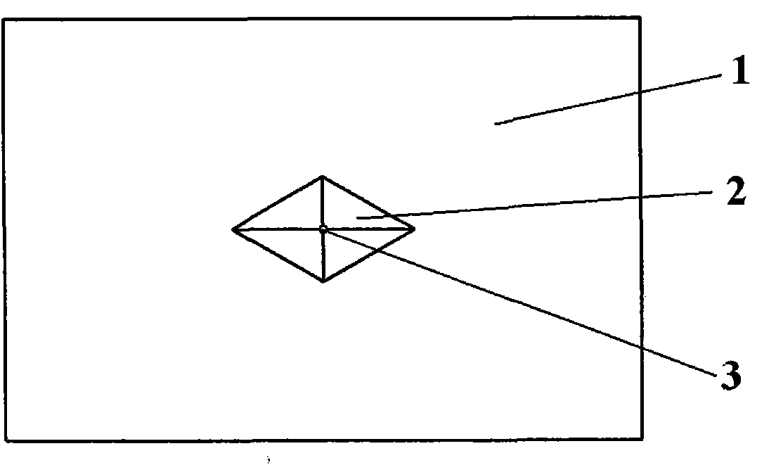
[0037] see figure 1 and figure 2 , figure 1 Shown is the sectional view of the air-floating thrust bearing in the equalizing chamber with two air-floating sliders in Embodiment 1; figure 2 Shown is a schematic diagram of the supporting surface of the air bearing slider with a single pressure equalization chamber in Example 1.

[0038] This pressure equalization chamber air bearing thrust bearing includes at least one air bearing slider 8 , and in this embodiment includes two air bearing sliders 8 . The support surface 1 of each air bearing slider is provided with at least one concave pyramid pressure equalization chamber 2, that is, the cross section of the pressure equalization chamber along the normal direction of the support surface 1 of the air bearing slider is pyramid-shaped. In this embodiment, each air bearing slider 8 is provided with a pyramid pressure equalization chamber 2 , and the pyramid pressure equalization chamber 2 is arranged at the center of the air b...

Embodiment 2

[0044] see image 3 and Figure 4 , image 3 Shown is the sectional view of the air-floating thrust bearing in the equalizing chamber with a single air-floating slider in Embodiment 2; Figure 4Shown is a schematic diagram of the supporting surface of the air bearing slider with four pressure equalization chambers in Example 2. This pressure equalization cavity air bearing thrust bearing includes an air bearing slider 8 and a base 9, and the air bearing slider 8 is circular. The support surface 1 of the air bearing slider is provided with four pyramidal pressure equalization chambers 2 along the circumferential direction, and an orifice 3 is respectively arranged at the apex of each pyramidal pressure equalization chamber 2 . The orifices 3 communicate with the air supply pipelines 13 inside the air bearing slider 8 respectively.

[0045] In addition, a circular vacuum chamber 4 is provided on the support surface 1 of the air bearing slider, and a vacuum hole 5 is opened i...


PUM


Abstract

The invention relates to an air bearing, in particular to a pressure-sharing cavity air thrust bearing which comprises at least one air floatation sliding block; a supporting surface of each air floatation sliding block is provided with at least one pyramid pressure-sharing cavity; the supporting surface is opposite to a substrate; the conical bottom surface of the pyramid pressure-sharing cavityis flush with the supporting surface; the peak of the pyramid pressure-sharing cavity is provided with an orifice; the orifice is communicated with an air supply pipeline which is arranged in the airfloatation sliding block; and the air supply pipeline is communicated with an external pressurizing air source. According to the invention, a diverging pyramid pressure-sharing cavity is adopted so that the high-pressure air more easily flows out along a parallel streamline when the high-pressure air flows in a bearing clearance through the orifice, the bearing vibration phenomenon educed by vortex close to the orifice is restrained, and the harm of micro vibration on the static and dynamic performance of the whole moving system is reduced.

Description

technical field [0001] The invention relates to an air-floating bearing, in particular to an air-floating thrust bearing with a pressure equalizing chamber. Background technique [0002] The air-bearing thrust bearing is the key component of the ultra-precision measurement and processing system, which has the advantages of cleanliness and no friction. With the development of air bearing thrust bearing applications such as nanotechnology, advanced optical devices and integrated circuits, higher requirements are placed on the static performance and positioning accuracy of air bearing thrust bearings. Pressure equalization cavity (groove) air-floating thrust bearing has become a hot research topic in recent years due to its characteristics of large load capacity, high rigidity, and low air consumption. The static and dynamic performance of its kinematic system, therefore, restricts the precision of the air bearing thrust bearing. [0003] In the traditional pressure equalizat...

Claims


Application Information

Patent Timeline
Patent Type & Authority Applications(China)
IPC IPC(8): F16C32/06
Inventor 王茜袁志扬
Owner SHANGHAI MICRO ELECTRONICS EQUIP (GRP) CO LTD
Learn More