Novel material transfer device

A technology for transferring devices and materials, applied to furnaces, lighting and heating equipment, furnace components, etc., can solve the problems of poor carrying capacity of transfer devices, slow material transfer speed, large material friction and wear, etc., to achieve large carrying capacity and material transfer Fast, reliable results

Inactive Publication Date: 2011-06-29
JIANGSU FENGDONG THERMAL TECH CO LTD
View PDF8 Cites 7 Cited by
  • Summary
  • Abstract
  • Description
  • Claims
  • Application Information

AI Technical Summary

Problems solved by technology

[0003] The technical problem to be solved by the present invention is to provide a new type of material transfer device to solve the problems existing in the prior art that under high temperature, the material friction and wear are large, the material transfer speed is slow, the transfer device has poor carrying capacity, and at the same time it can only realize a single The problem of feeding

Method used


Image

  • Novel material transfer device
  • Novel material transfer device
  • Novel material transfer device

Examples


Embodiment Construction

[0016] The present invention will be described in further detail below in conjunction with the accompanying drawings.

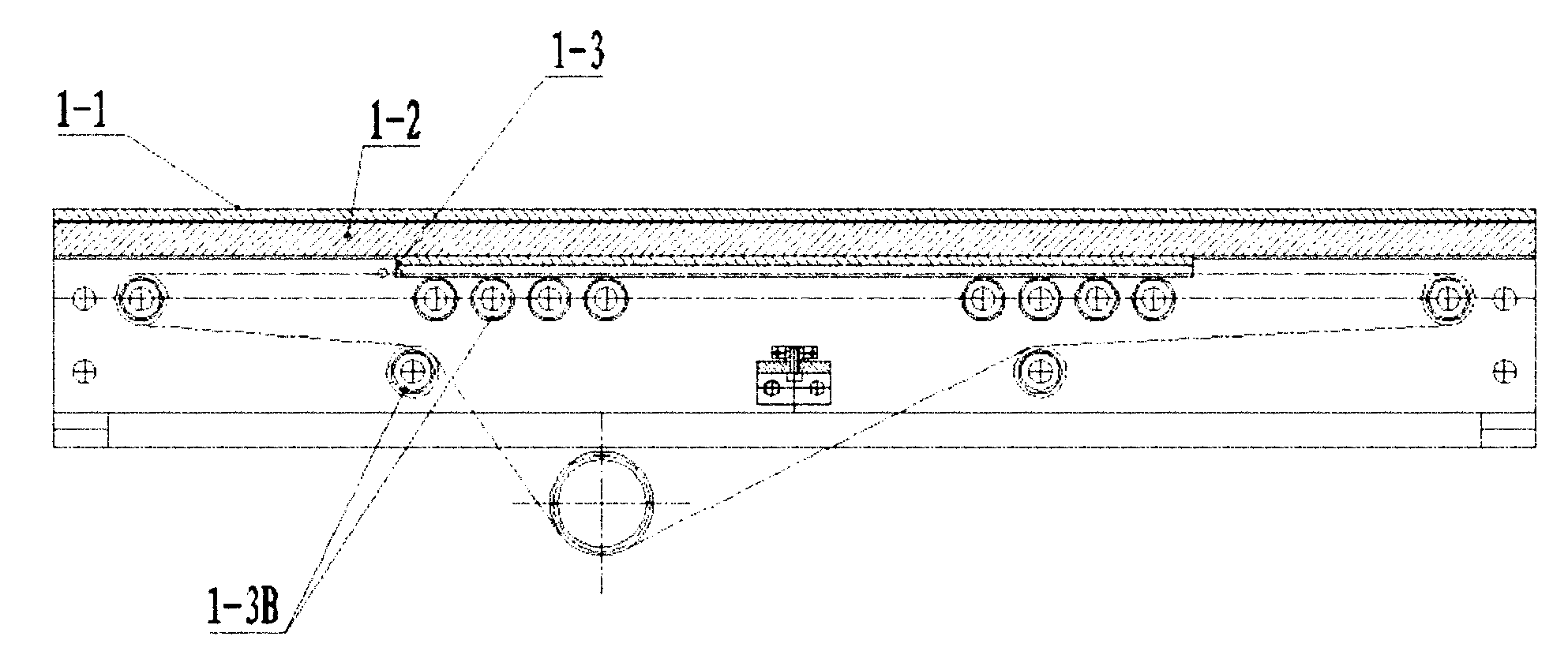
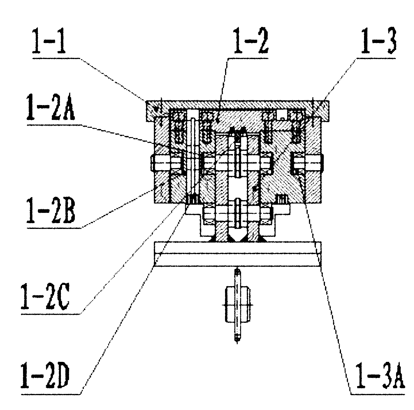
[0017] As shown in the figure, X-axis bidirectional drive mechanism 1: upper cantilever 1-1, lower cantilever 1-2, cantilever seat 1-3, lower cantilever drive mechanism 1-4, upper bevel gear set 1-5, transmission shaft 1-6, Lower bevel gear set 1-7; lower cantilever 1-2: inner roller guide 1-2A, outer roller guide 1-2B, sprocket rack 1-2C, left chain chute 1-2D, pulley system 1-3A, Chain pressure roller 1-3B; upper cantilever drive chain A, upper cantilever drive chain B; Z-axis vertical lifting mechanism 2: lifting frame 2-1, frame guide rail 2-2, lifting motor 2-3, chain drive 2-4 ; fixed connection point 3 on the upper cantilever; fixed connection point 4 on the cantilever seat.

[0018] see Figure 1 to Figure 8 , the present invention includes an X-axis bidirectional drive mechanism 1 and a Z-axis vertical lifting mechanism 2 . The X-axis bidirectiona...


PUM


Abstract

The invention discloses a novel material transfer device. The device is characterized by comprising an X-axis bidirectional driving mechanism and an Z-axis vertical lifting mechanism, wherein the X-axis bidirectional driving mechanism comprises an upper cantilever, a lower cantilever, a cantilever seat and a lower cantilever driving mechanism; the upper cantilever is connected above the lower cantilever in a rolling mode; the lower cantilever is connected above the cantilever seat in a rolling mode; the lower cantilever driving mechanism is connected with the lower cantilever through a transmission mechanism; the upper cantilever is drawn to do motion in the same direction through chain transmission when the lower cantilever moves on the cantilever seat; the cantilever seat of the X-axis bidirectional driving mechanism is fixed on the pedestal of the Z-axis vertical lifting mechanism; the Z-axis vertical lifting mechanism comprises a lifting stander, a stander guide rail, a lifting motor and a chain transmission; the lifting stander is connected in the stander guide rail in a rolling way; one end of the chain transmission is fixedly connected with the top end of the lifting stander, and the other end of the chain transmission is fixedly connected to the lower part of the lifting stander; and the lifting stander moves up and down in a Z-axis direction under the driving of the lifting motor.

Description

technical field [0001] The invention relates to a novel material transfer device, in particular to a feeding mechanism of a three-chamber horizontal heat treatment furnace, and belongs to the technical field of metal heat treatment equipment. Background technique [0002] At present, for the three-chamber horizontal heat treatment furnace, the drag chain method is often used for continuous feeding. In the horizontal furnace, the drag chain structure is used to drive the material basket to slide on the guide rail by traction. This method can only To realize the one-way transfer of materials in the X-axis direction, in the Y-axis direction, an additional lifting device should be installed to realize the lifting, so that the volume of the furnace is large, the temperature uniformity is not easy to ensure, and the friction between the guide rail and the material basket large, wears heavily on the material basket and guide rails, and affects the service life of the equipment; or ...

Claims


Application Information

Patent Timeline
Patent Type & Authority Applications(China)
IPC IPC(8): F27D3/00
Inventor 臧衡刘军
Owner JIANGSU FENGDONG THERMAL TECH CO LTD
Why Eureka
Try Eureka