Electrophoretic display device and drive method thereof

An electrophoretic display and driving method technology, applied in static indicators, instruments, nonlinear optics, etc., can solve the problems of high production cost and large leakage current of electrophoretic displays, so as to ensure display effect, maintain stable voltage, and reduce production costs. Effect

Active Publication Date: 2011-06-29
SHANGHAI TIANMA MICRO ELECTRONICS CO LTD
View PDF0 Cites 10 Cited by
  • Summary
  • Abstract
  • Description
  • Claims
  • Application Information

AI Technical Summary

Problems solved by technology

[0006] The invention provides an electrophoretic display and its driving method to solve the problem that the existing electrophoretic display needs to be equipped with a data driving circuit with a relatively large voltage driving range, resulting in high production costs
[0007] The present invention also provides an electrophoretic display and its driving method to solve the problem of large leakage current of the existing electrophoretic display

Method used


Image

  • Electrophoretic display device and drive method thereof
  • Electrophoretic display device and drive method thereof
  • Electrophoretic display device and drive method thereof

Examples


no. 1 example

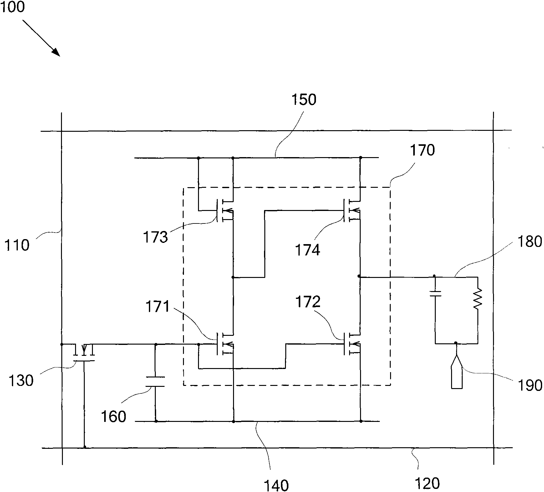
[0034] Please refer to figure 1 , which is a schematic structural diagram of the electrophoretic display provided by the first embodiment of the present invention, as figure 1 As shown, the electrophoretic display 100 includes: a plurality of data lines 110 and a plurality of gate lines 120 crossing each other, and a plurality of pixel units located at the intersections of the data lines 110 and the gate lines 120, wherein each pixel unit includes: a switch Element 130, first voltage line 140, second voltage line 150, storage unit 160, voltage selection unit 170 and pixel electrode 180, wherein storage unit 160 is connected to switching element 130 and first voltage line 140 respectively, voltage selection unit 170 The pixel electrodes 180 are respectively connected to the switching element 130 , the first voltage line 140 and the second voltage line 150 , and the voltage selection unit 170 is connected.

[0035] The storage unit 160 is a storage capacitor, and the storage un...

no. 2 example

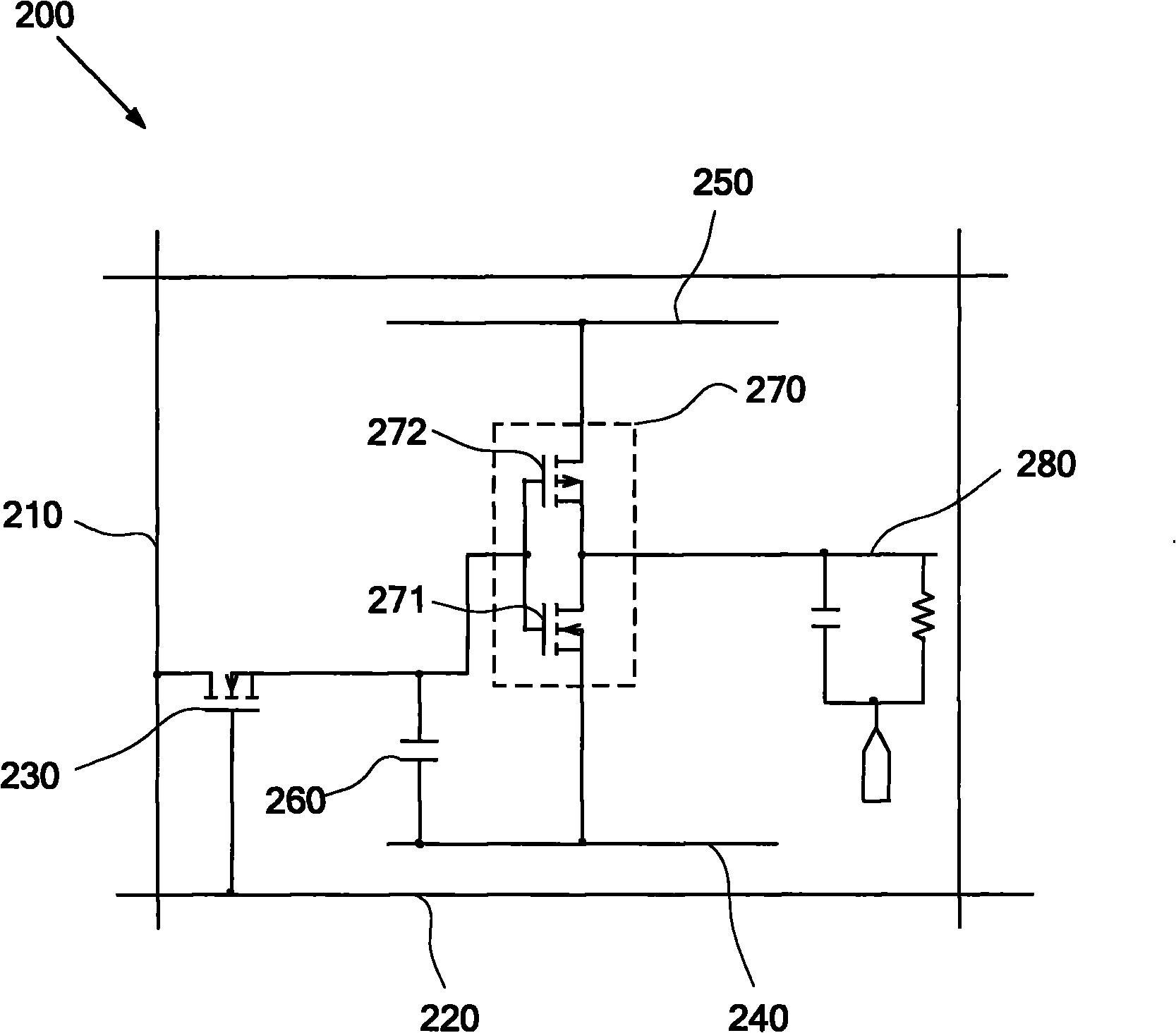
[0052] Please refer to image 3 , which is a schematic structural diagram of the electrophoretic display provided by the second embodiment of the present invention, as image 3 As shown, the electrophoretic display 200 includes: a plurality of data lines 210 and a plurality of gate lines 220 crossing each other, and a plurality of pixel units located at the intersections of the data lines 210 and the gate lines 220, wherein each pixel unit includes: a switch Element 230, first voltage line 240, second voltage line 250, storage unit 260, voltage selection unit 270 and pixel electrode 280, wherein storage unit 260 is connected to switching element 230 and first voltage line 240 respectively, voltage selection unit 270 The pixel electrodes 280 are connected to the voltage selection unit 270 respectively.

[0053] The storage unit 260 is a storage capacitor, and the storage unit 260 stores the voltage delivered by the switch element 230 so that the voltage can continue to be output...


PUM


Abstract

The invention discloses an electrophoretic display device and a drive method thereof. The electrophoretic display device comprises a plurality of data lines, a plurality of gate lines and a plurality of pixel units, wherein the data lines and the gate lines are mutually intersected; the pixel units are positioned at the intersections of the gate lines and the data lines; and each pixel unit comprises a switch element, a first voltage line, a second voltage line, a voltage selecting unit and a pixel electrode, wherein the voltage selecting unit is respectively connected with the switch element, the first voltage line and the second voltage line, and the pixel electrode is connected with the voltage selecting unit. The electrophoretic display device disclosed by the invention is not required to be equipped with a data driven circuit with a larger voltage driving range, thereby lowering the production cost, and reducing the leakage current.

Description

technical field [0001] The invention relates to the field of electrophoretic display, in particular to an electrophoretic display and a driving method thereof. Background technique [0002] At present, the phenomenon of swimming of charged particles dispersed in a liquid due to an applied electric field, that is, the so-called electrophoretic phenomenon, has been well known, and an electrophoretic display utilizing the electrophoretic phenomenon has been developed, which combines the advantages of ordinary paper and electronic displays. Advantages, it is both readable and portable, and has the characteristics of wide viewing angle and flexibility, so electrophoretic displays have been confirmed to replace traditional paper media. [0003] Generally, an existing electrophoretic display includes: a first substrate, a second substrate, and an electronic ink layer arranged between the first substrate and the second substrate. Wherein, a plurality of data lines and a plurality o...

Claims


Application Information

Patent Timeline
IPC IPC(8): G09G3/34G02F1/167
Inventor 李忠丽罗熙曦马骏吴勇
Owner SHANGHAI TIANMA MICRO ELECTRONICS CO LTD
Why Eureka
Try Eureka