Self-starting permanent magnet motor provided with composite material starting conducting bars

A technology of permanent magnet motors and composite materials, which is applied to magnetic circuits characterized by magnetic materials, synchronous machines, electrical components, etc. It can solve the problem that the rotor cannot use deep grooves or double-layer guide bar structures, and achieve anti-demagnetization The effect of superior ability

Inactive Publication Date: 2012-11-21
NORTH CHINA ELECTRIC POWER UNIV (BAODING)
View PDF0 Cites 1 Cited by
  • Summary
  • Abstract
  • Description
  • Claims
  • Application Information

AI Technical Summary

Problems solved by technology

However, in the self-starting permanent magnet motor, due to the existence of permanent magnets, it is impossible for the rotor to adopt a deep groove or double-layer guide bar structure

Method used


Image

  • Self-starting permanent magnet motor provided with composite material starting conducting bars
  • Self-starting permanent magnet motor provided with composite material starting conducting bars
  • Self-starting permanent magnet motor provided with composite material starting conducting bars

Examples


Embodiment 1

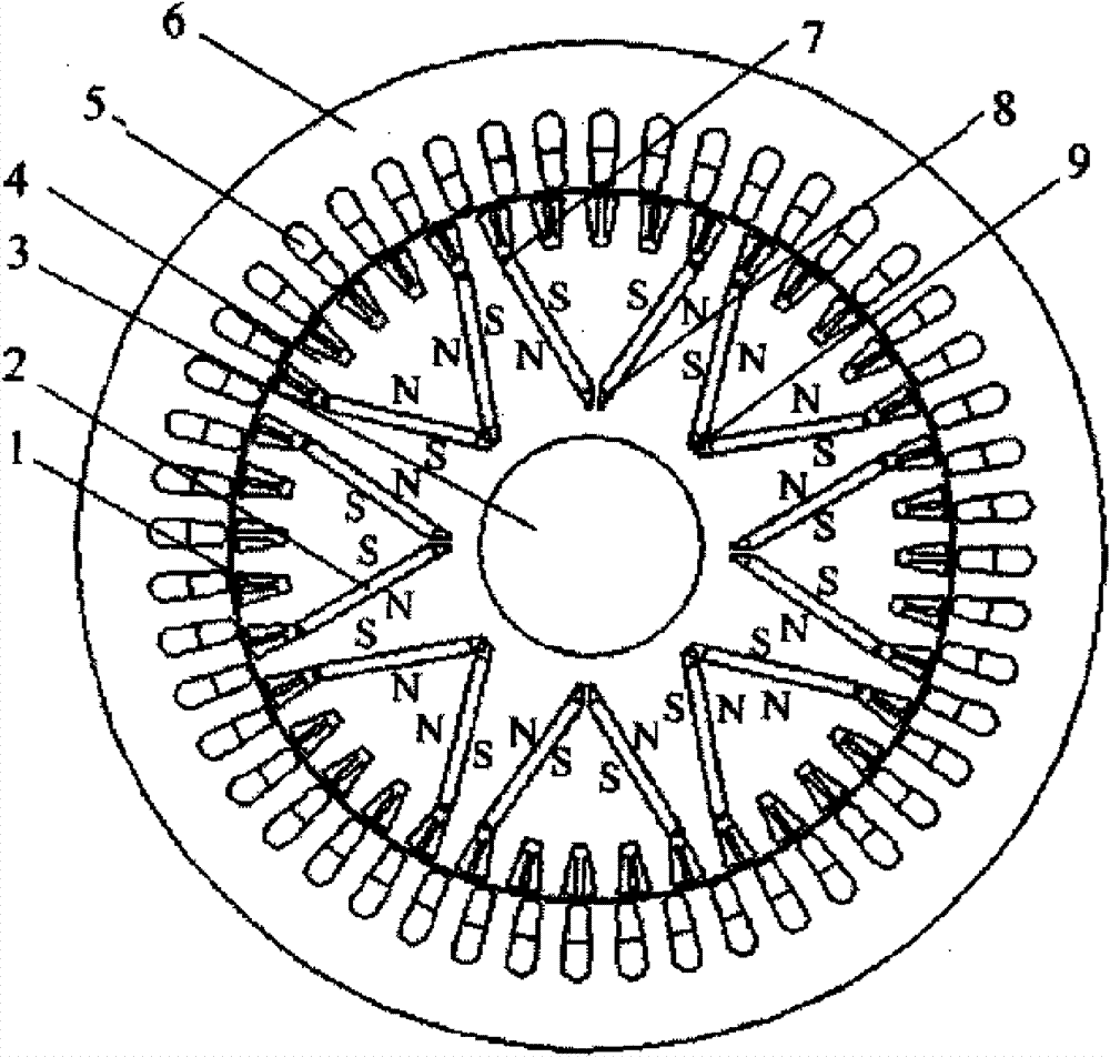
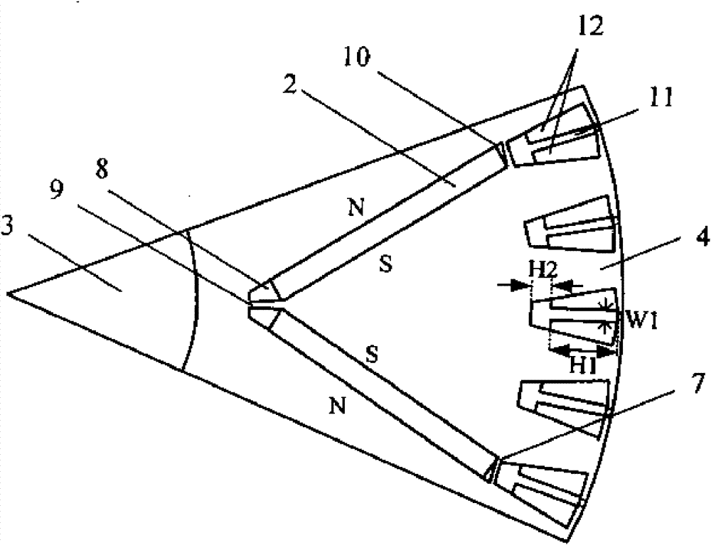
[0032] Such as figure 2 Shown is an enlarged schematic diagram of a magnetic pole of a permanent magnet motor rotor with a composite starting bar. Each squirrel cage starting bar 1 includes two materials: brass and copper-iron alloy materials. The brass guide bar 11 has a convex structure and is located in the middle of the bottom and upper part of the rotor slot, and the copper-iron alloy material 12 is located on both sides of the upper part of the rotor slot. The two ends of each squirrel cage starter bar 1 are short-circuited outside the core of the rotor iron 4 through welded brass end rings; in this embodiment, the conductivity of the copper-iron alloy material is 6825.4726S, which is between copper and iron. The height of the brass at the bottom of the rotor slot is 3mm, the height of the upper brass is 16mm, and the width is 2mm.

[0033] Compared figure 1 with 3 It can be seen that the biggest difference between the composite material starter bar permanent magnet motor ...

Embodiment 2

[0038] The overall structure of the permanent magnet motor of the composite starting bar of the second embodiment is the same as that of the first embodiment. The difference is that the structure of the brass in the rotor bar is different from that of the first embodiment. figure 2 In the enlarged schematic diagram of one magnetic pole of the permanent magnet motor rotor of the composite starting guide bar shown, the middle part of the squirrel cage starting guide bar 1 is all brass guide bars 11, and the two sides of the guide bar groove are copper-iron alloy materials 12, so the squirrel cage The processing of the starting guide bar 1 is also simpler than that of the first embodiment. In Example 2, the width of the brass is selected to be 2 mm. The starting current multiple of the permanent magnet motor in this embodiment is 7.56, the locked-rotor torque multiple is 3.2, and the minimum magnetic density at a certain point of the permanent magnet during the starting process is...


PUM


Abstract

The invention discloses a self-starting permanent magnet motor provided with composite material starting conducting bars, which belongs to the technical field of permanent magnet motors. A rotor of the permanent magnet motor has a stamping type structure; a permanent magnet is arranged on the inner side of a rotor core, N and S magnetic poles are arranged alternately; a permanent magnet rotor adopts a magnetic pole structure of a U type, V type or mixed type magnetic circuit; composite material rat cage starting conducting bars are uniformly distributed close to the surface of the rotor core;and the composite material rat cage starting conducting bars is made of two types of materials including brass and copper-iron alloy. The brass is positioned on a middle part between the bottom part of a rotor groove and the upper part of the rotor groove; two side parts of the upper part of the rotor groove are made of the copper-iron alloy; or the middle part of the rotor groove is made of the brass, while the two sides of the rotor groove are made of the copper-iron alloy. Two ends of each composite material starting conducting bar are shorted out outside the rotor core through a welded brass end ring. Through the adjustment of the structure sizes of the brass and the copper-iron alloy materials, the obtained permanent magnet motor has a small starting current multiple and strong demagnetization resistance, can be started smoothly, and is suitable for workplaces requiring long-time continuous operation.

Description

Technical field [0001] The invention belongs to permanent magnet motor technology, and particularly relates to a self-starting permanent magnet motor with a composite material starting guide bar. Background technique [0002] AC asynchronous motors are widely used in the industrial field because they have the advantages of easy manufacturing, sturdiness and durability, and low price. However, asynchronous motors need to provide excitation current from the stator windings, and their power factor is not very high, and the efficiency of the motor is not high due to the existence of rotor copper loss, which is especially serious for small and medium-sized asynchronous motors or when the motor is lightly loaded. Compared with asynchronous motors, permanent magnet synchronous motors are equipped with permanent magnets on the rotor, which does not require external excitation, which can significantly improve the power factor; when the permanent magnet motors are operating in a steady sta...

Claims


Application Information

Patent Timeline
Patent Type & Authority Patents(China)
IPC IPC(8): H02K21/46H02K1/27H02K1/02
Inventor 刘明基卢伟甫宋中阳罗应立张健
Owner NORTH CHINA ELECTRIC POWER UNIV (BAODING)
Why Eureka
Try Eureka