Top-level impeller on condensate extraction pump for nuclear power station

A first-stage impeller and condensate pump technology, which is applied to components, pumps, and pump components of pumping devices for elastic fluids, and can solve the problems of high weight and cost of pump sets, poor stability of pump sets, and high pressure in straight pipes, etc. problem, to achieve the effect of reducing the necessary NPSH, reducing hydraulic loss, and reducing the relative velocity of the inlet

Inactive Publication Date: 2011-07-06
SHANGHAI APOLLO MACHINERY
View PDF5 Cites 11 Cited by
  • Summary
  • Abstract
  • Description
  • Claims
  • Application Information

AI Technical Summary

Problems solved by technology

The entire pump body structure of the condensate pump in the prior art is: a double-suction volute casing, a secondary guide vane, a final guide vane, a straight pipe, and a water outlet casing connected sequentially from bottom to top; The guide vane is far away from the driving end of the pump shaft, and the vibration caused by the rotation of the secondary impeller and the final impeller is relatively large, which makes the straight pipe bear a large pressure. Therefore, a straight pipe with a large wall thickness is used. The stability of the group is poor, and the overall weight and cost of the pump group are high

Method used


Image

  • Top-level impeller on condensate extraction pump for nuclear power station
  • Top-level impeller on condensate extraction pump for nuclear power station
  • Top-level impeller on condensate extraction pump for nuclear power station

Examples


Embodiment Construction

[0014] In order to better understand the technical solution of the present invention, it will be described in detail below through specific embodiments in conjunction with the accompanying drawings:

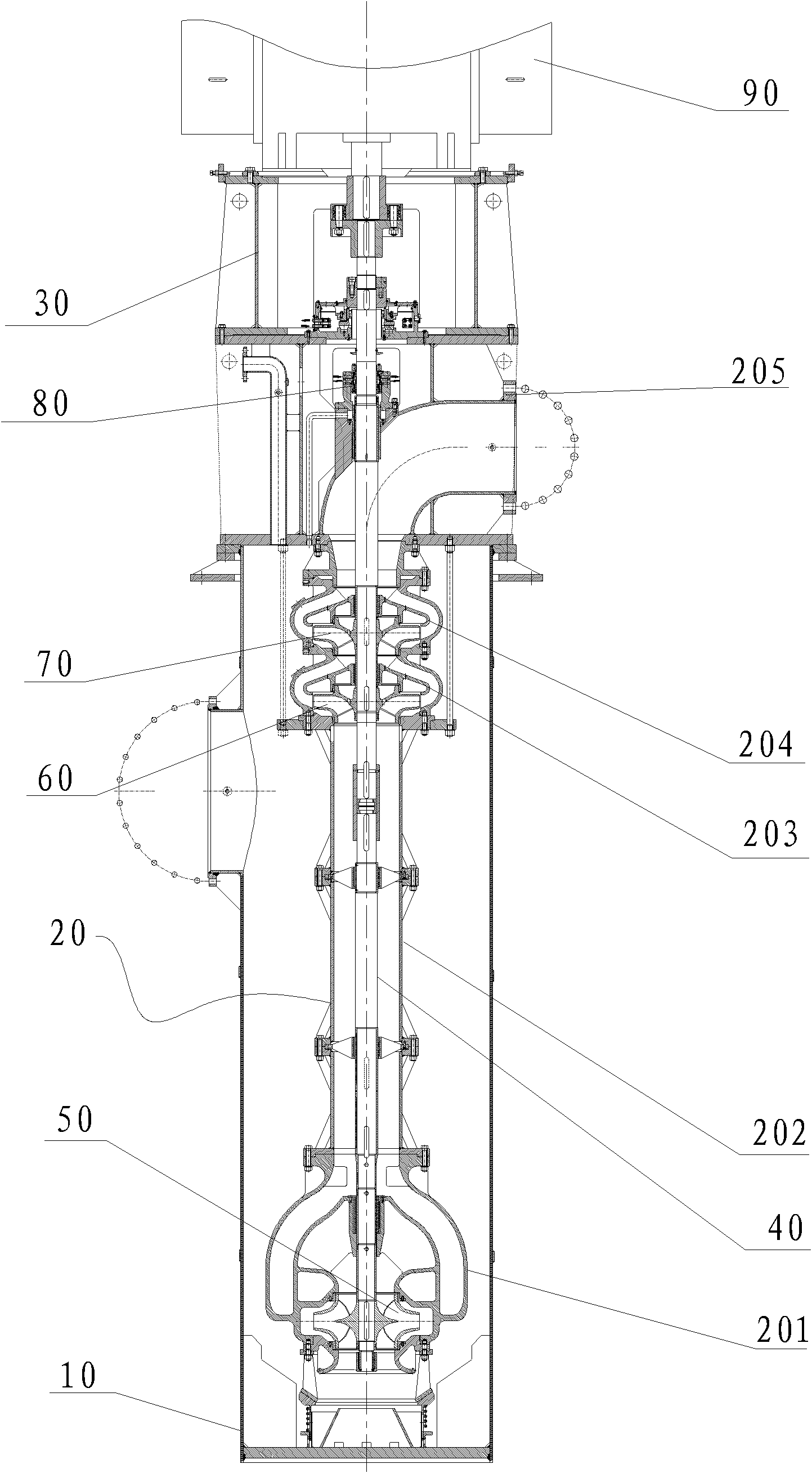
[0015] see figure 1 , The condensate pump includes a vertical outer cylinder 10 , pump body 20 , motor frame 30 , pump shaft 40 , first stage impeller 50 , secondary impeller 60 , last stage impeller 70 , mechanical seal 80 , bearing assembly and motor 90 . The pump body 20 includes a double-suction volute case 201, a straight pipe 202, a secondary guide vane 203, a final guide vane 204, a water outlet housing 205, a first-stage impeller 50, and a secondary impeller that are coaxially connected to each other in sequence from bottom to top. 60 and the last-stage impeller 70 are fixedly sleeved on the pump shaft 40 and are respectively arranged in the inner cavity of the double-suction volute case 201 , the secondary guide vane 202 and the final-stage guide vane 203 .

[0016] see...


PUM


Abstract

The invention discloses a top-level impeller on a condensate extraction pump for a nuclear power station, which comprises a hub, a front cover plate, a rear cover plate and a plurality of blades, wherein the inner end surface of the hub is a cylindrical surface, and the outer end surface of the hub is formed by connecting two sections of trumpet-shaped curved surfaces which are in the same shape and have the same size back to back; the front cover plate and the rear cover plate are trumpet-shaped curved plates which are in the same shape and have the same size; the inner end surface of the front cover plate and the rear cover plate are formed by sequentially connecting a small section of straight surface, a section of first curved surface of which the curvature radius is R1 and a second curved surface of which the curvature radius is R2; the R2 is more than R1; the front cover plate and the rear cover plate are coaxially arranged at the periphery of the hub back to back to ensure that the inlet diameter and the outlet diameter of the top-level impeller are the same as each other; the front edge and the rear edge of each blade are connected on the inner end surfaces of the front cover plate and the rear cover plate respectively; and a V-shaped inner edge formed in the middle of each blade is connected on the outer end surface of the hub to form a double-suction impeller. The top-level impeller can reduce necessary net positive suction head of a small pump and has higher cavitation resistance.

Description

technical field [0001] The invention relates to a first-stage impeller on a condensate pump used in a nuclear power plant. Background technique [0002] Condensate pumps are used to pump condensate in nuclear power plants. The suction side of the pump is highly vacuumed, which is prone to cavitation and air inhalation. Therefore, the requirements for anti-cavitation of the pump are particularly high, and the head is as high as 150 to 350 meters. The entire pump body structure of the condensate pump in the prior art is: a double-suction volute casing, a secondary guide vane, a final guide vane, a straight pipe, and a water outlet casing connected sequentially from bottom to top; The guide vane is far away from the driving end of the pump shaft, and the vibration caused by the rotation of the secondary impeller and the final impeller is relatively large, which makes the straight pipe bear a large pressure. Therefore, a straight pipe with a large wall thickness is used. The st...

Claims


Application Information

Patent Timeline
Patent Type & Authority Applications(China)
IPC IPC(8): F04D29/22
Inventor 陆金琪
Owner SHANGHAI APOLLO MACHINERY
Why Eureka
Try Eureka