Asynchronous transmission multistage centrifugal pump

A centrifugal pump and multi-stage pump technology, which is applied in the field of centrifugal pumps, can solve the problems of reducing the speed of multi-stage pumps, decreasing efficiency, and the limited range of reduction, so as to reduce NPSH, improve sealing effects, and reduce leakage points. Effect

Active Publication Date: 2014-12-31
SHENYANG QIYUAN INDAL PUMP MFG
View PDF6 Cites 0 Cited by
  • Summary
  • Abstract
  • Description
  • Claims
  • Application Information

AI Technical Summary

Problems solved by technology

[0005] 4. Reduce the speed of the multi-stage pump
[0006] Traditional pumps only use the first-stage double-suction impeller or inducer to reduce the NPSH of the pump, and the reduction range is limited.
At the same time, in some actual engineering installations, it is not allowed to use vertical pumps due to the limitations of the installation location and civil foundation.
Reduce the NPSH by reducing the speed of the multi-stage pump, by the formula It is known that when the speed decreases, the head will drop greatly by the power of 2, resulting in too many stages of the pump, wasting costs, and when the speed decreases, the efficiency will also decrease.

Method used


Image

  • Asynchronous transmission multistage centrifugal pump
  • Asynchronous transmission multistage centrifugal pump
  • Asynchronous transmission multistage centrifugal pump

Examples


Embodiment Construction

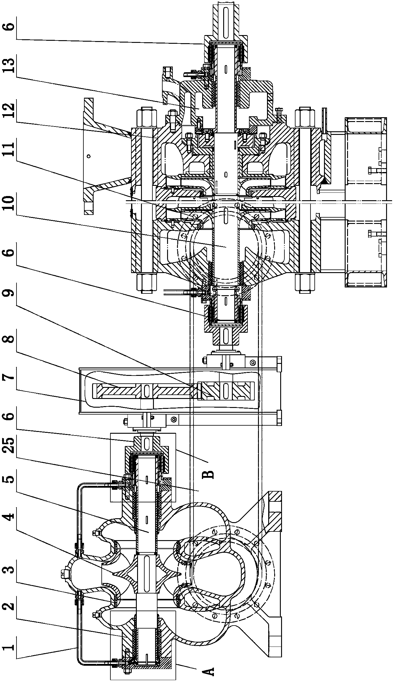
[0022] The present invention includes a first-stage pump body 2, the first-stage pump body 2 is provided with a double-suction impeller 4 through a first-stage shaft 5, and is characterized in that: the water outlet end of the first-stage pump body 2 is connected to the multi-stage pump body 12 through a water pipe 25 The water inlet is connected; the multistage pump body 12 is provided with a multistage impeller 11 through a multistage shaft 10; the multistage shaft 10 is connected with the first stage shaft 5 through a gearbox 7.

[0023] As a preferred solution of the present invention, the first stage shaft 5 is connected to the end of the gearbox 7 with a low speed; the multistage shaft 10 is connected to the end of the gearbox 7 with a high speed.

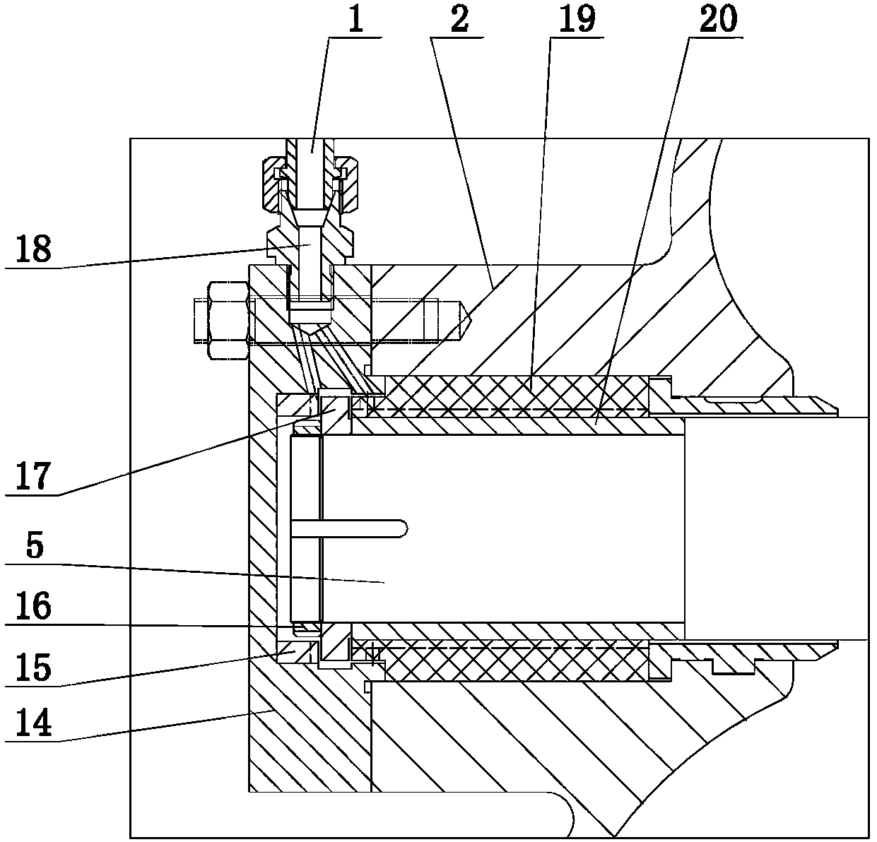
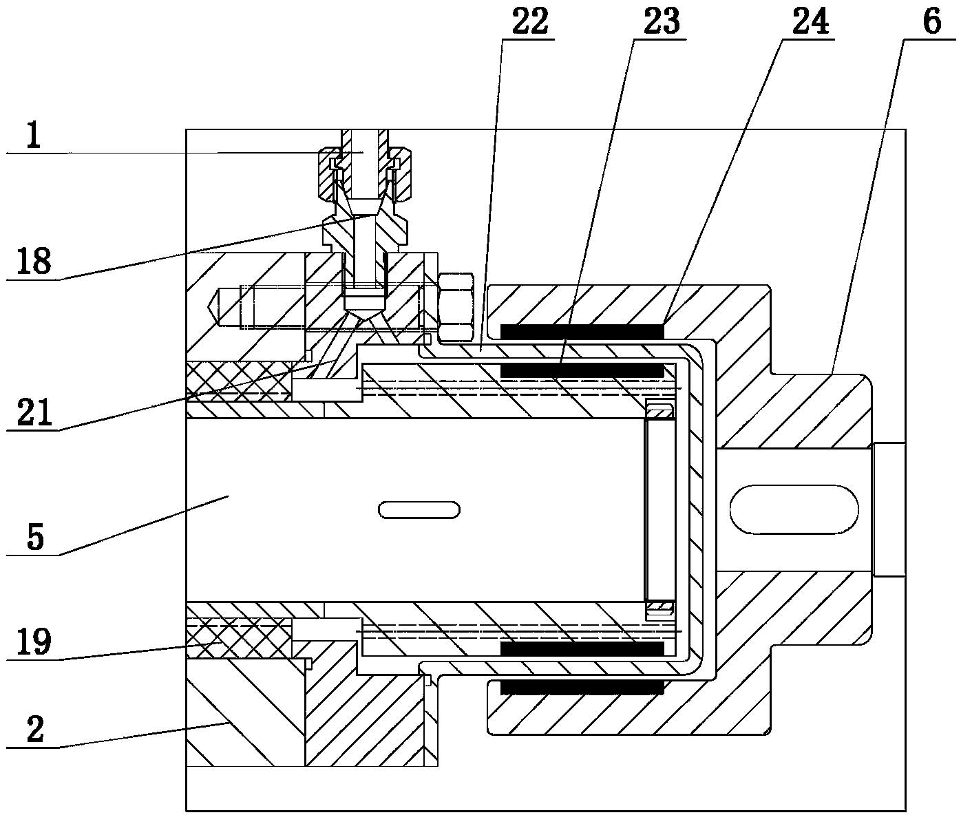
[0024] As another preferred solution of the present invention, one end of the first stage shaft 5 and both ends of the multistage shaft 10 are provided with a magnetic coupling 6; the first stage shaft 5 and the multistage sha...


PUM


Abstract

The invention discloses an asynchronous transmission multistage centrifugal pump, belongs to the technical field of centrifugal pumps, and particularly relates to asynchronous transmission multistage centrifugal pumps. The asynchronous transmission multistage centrifugal pump comprises a primary pump body. A double-sided impeller is arranged in the primary pump body via a primary shaft. The asynchronous transmission multistage centrifugal pump is characterized in that a water outlet end of the primary pump body is connected with a water inlet end of a multistage pump body; a multistage impeller is arranged in the multistage pump body via a multistage shaft; the multistage shaft is connected with the primary shaft by a gearbox. The asynchronous transmission multistage centrifugal pump has the advantages that the net positive suction head can be greatly reduced without changing the number of stages of the centrifugal pump, and the lift of the horizontal asynchronous transmission multistage centrifugal pump can be guaranteed.

Description

technical field [0001] The invention belongs to the technical field of centrifugal pumps, in particular to an asynchronous transmission multistage centrifugal pump. Background technique [0002] In order to achieve high head output, most of them are realized by multistage centrifugal pumps. Traditional multi-stage centrifugal pumps are installed on a shaft with multi-stage impellers step by step, and the lifts are accumulated to obtain high lifts. In some installations in the petrochemical industry, the requirements for pumps are strict, not only high head, but also extremely low NPSH, high efficiency and energy saving, no leakage and so on. In order to achieve low NPSH, the traditional method is: 1. Select the first-stage double-suction impeller. [0003] 2. Add an inducer at the suction end of the first stage impeller. [0004] 3. Adopt a vertical multi-stage pump, and set the first-stage impeller of the pump in a low pump pit. [0005] 4. Reduce the speed of the multi...

Claims


Application Information

Patent Timeline
Patent Type & Authority Applications(China)
IPC IPC(8): F04D1/06F04D29/046
Inventor 李斌
Owner SHENYANG QIYUAN INDAL PUMP MFG
Why Eureka
Try Eureka