Monopropellant thruster electromagnetic valve

A thruster and solenoid valve technology, applied in the field of solenoid valves, can solve the problems of reduced satellite orbit control and attitude control accuracy, unstable switching performance of solenoid valves, and reduced leakage rate of solenoid valves, etc., so as to improve product qualification rate and save production. Test cost and effect of improving cleanliness

Active Publication Date: 2011-07-06
BEIJING INST OF CONTROL ENG
View PDF0 Cites 23 Cited by
  • Summary
  • Abstract
  • Description
  • Claims
  • Application Information

AI Technical Summary

Problems solved by technology

During the life of the satellite, the switching times of the solenoid valve are generally between 100,000 and 1 million times. The friction caused by frequent switching will produce a lot of excess. If the excess accumulates at the valve port, it will easily lead to poor sealing reliability and internal leakage rate of the solenoid valve. Reduced, in severe cases, it will cause propellant leakage and cause satellite failure
If the excess material accumulates in the injector...

Method used


Image

  • Monopropellant thruster electromagnetic valve
  • Monopropellant thruster electromagnetic valve

Examples


Embodiment Construction

[0018] The invention will be further described below in conjunction with the accompanying drawings.

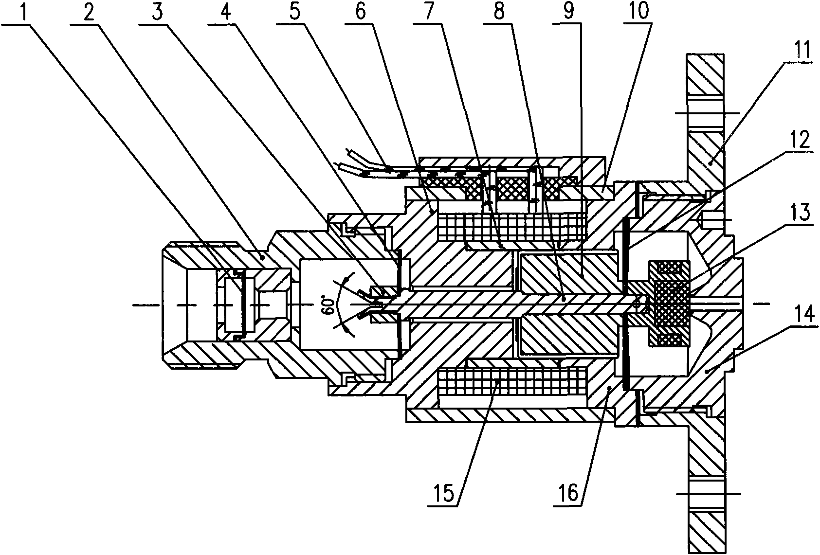
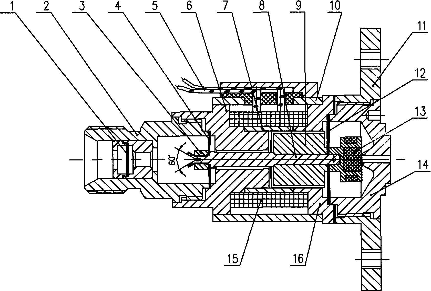
[0019] Such as figure 1 As shown, the single-component thruster solenoid valve of the present invention includes a filter assembly 1, an inlet joint 2, a lock nut 3, a guide spring 4, a lead wire 5, an upper valve body 6, a magnetic isolation ring 7, an armature rod 8, An armature 9, an outer conducting magnet 10, a flange 11, a sealing spring 12, a baffle 13, a valve seat 14, a coil 15 and a lower valve body 16.

[0020] The armature rod 8 , armature 9 , sealing spring 12 and baffle 13 connected in sequence form an armature assembly, which is located in the valve body framework formed by connecting the upper valve body 6 , the magnetic isolation ring 7 and the lower valve body 16 . The upper valve body 6 and the lower valve body 16 are two sections of magnetically conductive material, and the magnetic isolation ring 7 is a section of nonmagnetically conductive material. The ...


PUM


Abstract

The invention discloses a monopropellant thruster electromagnetic valve, which comprises a filter component (1), an inlet joint (2), a locking nut (3), a guide spring (4), a lead wire (5), an upper valve body (6), a magnetic isolation ring (7), an armature lever (8), an armature (9), an external magnetizer (10), a flange plate (11), a sealing spring (12), a baffle plate (13), a valve seat (14), a coil (15) and a lower valve body (16), wherein the guide spring (4) is a single-arm circular flat spring; and the sealing spring (12) is a double-arm S-shaped circular flat spring. Two flat springs with large radial stiffness and different axial stiffnesses are adopted for joint supporting, and the armature component is suspended in a valve body of the electromagnetic valve and not in contact with the inner wall of the electromagnetic valve, thereby avoiding the possibility of self-pollution of the electromagnetic valve caused by redundancy materials generated by friction between the armature component and a framework of the valve body during the opening and the closing of the electromagnetic valve, and improving reliability in the opening and the closing of the electromagnetic valve and sealing reliability.

Description

technical field [0001] The invention relates to the technical field of satellite propulsion, in particular to an electromagnetic valve controlled by an electric signal and driven by a solenoid electromagnet. Background technique [0002] Solenoid valves are used in satellite propulsion subsystems for thruster propellant control. The traditional solenoid valve uses the springback force of a coil spring or a single leaf spring to seal the valve port. Due to the radial asymmetry of the springback force, it is easy to cause the entire armature or one end of the armature to contact the inner wall of the valve. When the valve is switched on and off under load, the armature is subjected to the joint action of magnetic field force and hydraulic pressure, which makes the armature assembly rub against the inner wall of the valve. During the life of the satellite, the switching times of the solenoid valve are generally between 100,000 and 1 million times. The friction caused by freque...

Claims


Application Information

Patent Timeline
IPC IPC(8): F16K31/06
Inventor 于金盈陈健武葱茏毛威
Owner BEIJING INST OF CONTROL ENG
Why Eureka
Try Eureka