
Material testing machine-based ball screw assembly axial static stiffness testing clamp

A technology of ball screw pair and material testing machine, applied in the direction of analyzing materials, using stable tension/pressure to test material strength, measuring devices, etc., can solve the problems of high cost, single loading form, immature technical means, etc. To achieve the effect of improved precision and high precision

Inactive Publication Date: 2011-07-06
SOUTHEAST UNIV
View PDF4 Cites 15 Cited by
  • Summary
  • Abstract
  • Description
  • Claims
  • Application Information

AI Technical Summary

Problems solved by technology

However, since the load direction in the actual work of the ball screw pair is in the axial direction, and the deformation is at the micron level, it is difficult to test the axial static stiffness of the ball screw pair
NSK company uses a pair of synchronously driven precision ball screw pairs to load. In the 1990s, it developed a ball screw pair axial contact stiffness measuring machine; in China, Shandong Jianzhu University began to try to design a special hydraulic system for axial loading in 2008. , through the acquisition and processing of the load cell and displacement sensor signals to detect the axial static stiffness of the ball screw pair, the device needs to borrow additional hydraulic pressure and T-shaped guide rails to control the rotation of the screw, and at the same time only To pressurize the lead screw, the loading form is single, the cost is relatively large, and the technical means are still in the immature stage

Method used


Image

  • Material testing machine-based ball screw assembly axial static stiffness testing clamp
  • Material testing machine-based ball screw assembly axial static stiffness testing clamp
  • Material testing machine-based ball screw assembly axial static stiffness testing clamp

Examples


Embodiment Construction

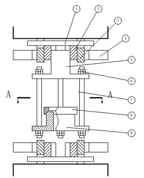
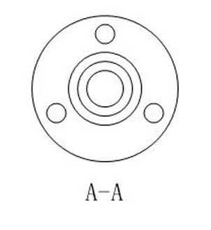
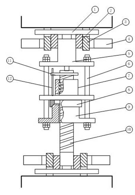
[0015] A test fixture for axial static stiffness of a ball screw pair based on a material testing machine, comprising: a pull-up block 5, on which at least two pull rods 6 are arranged, and one end of the pull rod 6 is connected to the pull-up block 5 , the other end of the pull rod 6 is connected with a briquetting block 9, the briquetting block 9 is provided with an inner hole 91 for the ball screw to be tested to pass through, and the upper end of the briquetting block 9 is a round chamfer 92. The briquetting block 9 is provided with an adjusting block 8, and the adjusting block 8 is provided with an inner hole 81 through which the ball screw to be measured passes. The rounded corners 92 are in contact with each other, and the adjusting block 8 is provided with a nut 7 for connecting the ball screw to be tested. In this embodiment, three pull rods 6 are provided on the upper pull block 5 .

[0016] The measurement method is as follows:

[0017] Using this fixture to measur...


PUM


Abstract

The invention relates to a material testing machine-based ball screw assembly axial static stiffness testing clamp. The clamp comprises a pull-up block, wherein the pull-up block is provided with at least two pull rods; one end of each pull rod is connected with the pull-up block, and the other end of each pull rod is connected with a pressing block; the pressing block is provided with an inner hole through which a ball screw to be tested passes; the upper end of the pressing block is provided with a round chamfer; the pressing block is provided with an adjusting block; the adjusting block is provided with an inner hole through which the ball screw to be tested passes, the lower part of the inner hole is provided with a conical hole and the conical hole is contacted with the round chamfer of the pressing block; and the adjusting block is provided with a nut for connecting the ball screw to be tested. Through the clamp, the axial static stiffness of the ball screw assembly can be tested on the conventional material testing machine; the cost for testing the axial static stiffness of the ball screw assembly is reduced; the testing accuracy is improved; and the clamp has the advantage of compact structure.

Description

technical field [0001] The invention belongs to the technical field of stiffness testing, in particular to the axial static stiffness testing technology of a ball screw pair, which is used for measuring the axial static stiffness performance index of the ball screw pair on a material testing machine. Background technique [0002] Axial static stiffness R is defined as the ability to resist axial deformation (the load required for unit deformation), which represents the amount of deformation in the axial direction under the action of axial force for Axial force required for ( Unit: N). In summary, the static axial stiffness test of the ball screw pair involves two key technologies, namely the application of axial force and the test of axial deformation. However, since the load direction of the ball screw pair is in the axial direction and the deformation is at the micron level in the actual work of the ball screw pair, it is difficult to test the axial static stiffnes...

Claims


Application Information

Patent Timeline
IPC IPC(8): G01N3/04G01N3/14
Inventor 汤文成王洁璐陈晶晶李东君
Owner SOUTHEAST UNIV
Learn More