
Flow field plate

A flow field plate and flow channel technology, applied in the field of flow field plate, can solve the problems affecting fuel cell performance, reaction fluid flow rate and uneven concentration distribution, so as to avoid uneven concentration distribution, improve overall performance, and reduce flow rate. The effect of resistance

Inactive Publication Date: 2011-07-06
IND TECH RES INST
View PDF0 Cites 0 Cited by
  • Summary
  • Abstract
  • Description
  • Claims
  • Application Information

AI Technical Summary

Problems solved by technology

[0003] In the flow field plate of a general small fuel cell, the size of the flow channel and manifold is usually smaller than that of a large fuel cell, so the flow resistance of the reaction fluid is relatively increased, which will lead to the flow of the reaction fluid entering the flow field plate. Inhomogeneous distribution of rate and concentration will affect the performance of fuel cells

Method used


Image

  • Flow field plate
  • Flow field plate
  • Flow field plate

Examples


Embodiment Construction

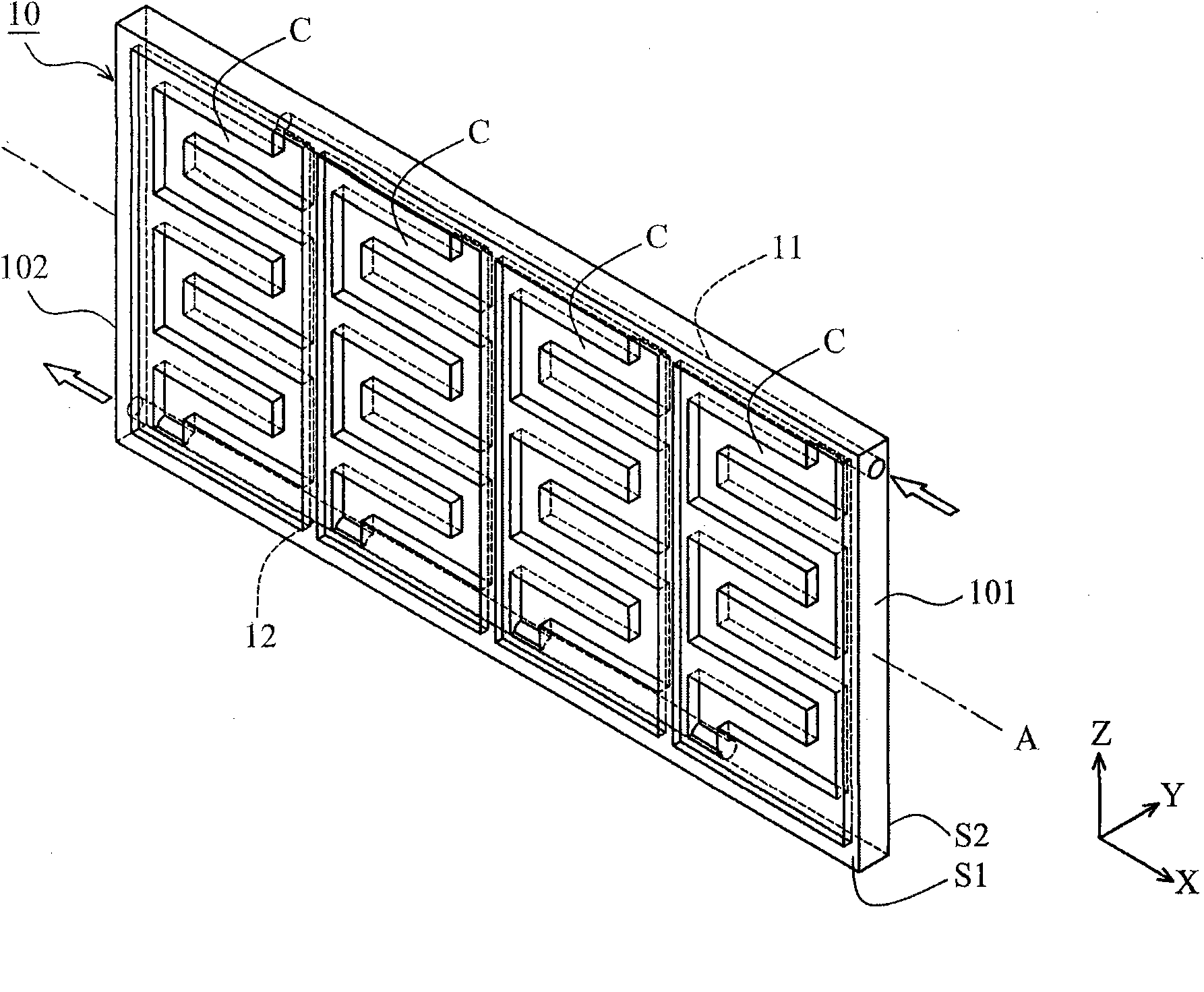
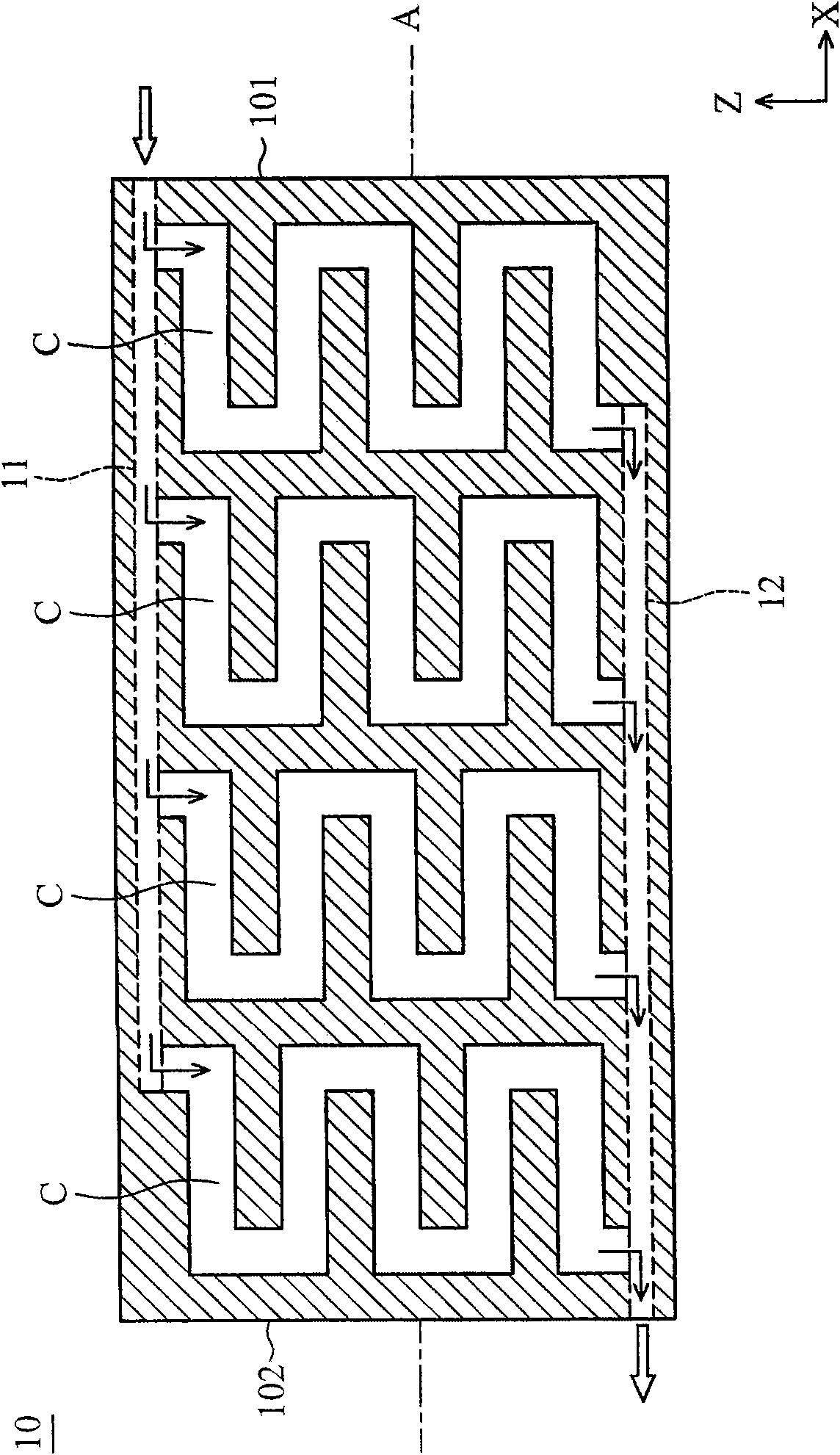
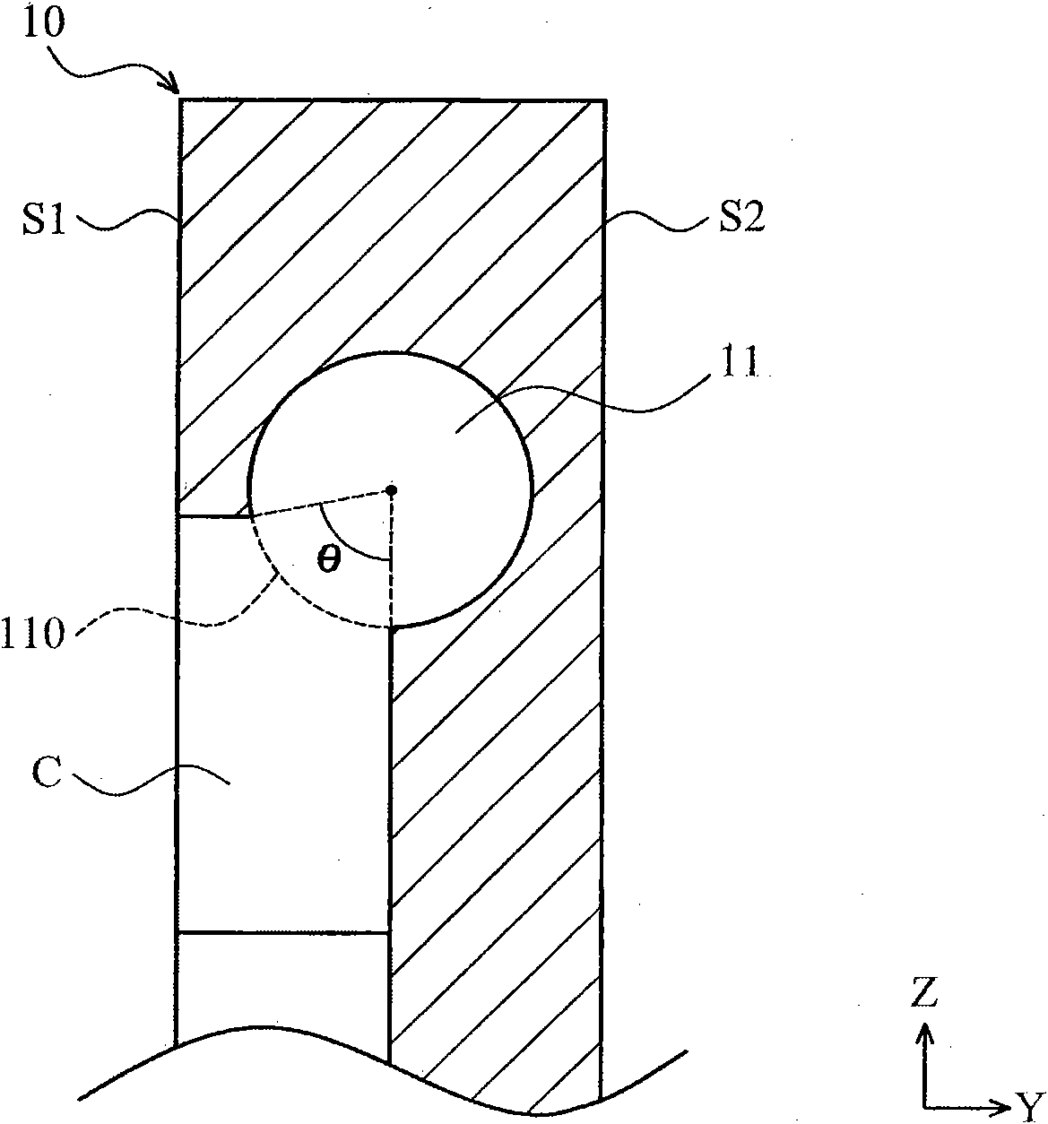
[0056] Please refer to it first Figure 1A , 1B , The flow field plate 10 of an embodiment of the present invention is mainly arranged in a flat fuel cell device, which is roughly a rectangular structure, and a single or multiple flow channels C ( flow channel), in addition, a first manifold 11 and a second manifold 12 are formed inside the flow field plate 10. Such as Figure 1A As shown, the aforementioned flow channels C are arranged along the direction of a central axis A of the flow field plate 10 and are exposed on the first side S1 of the flow field plate 10, and the aforementioned first and second manifolds 11 and 12 are formed in the flow field. The inside of the plate 10 is approximately parallel to the central axis A, and the first and second manifolds 11 and 12 communicate with the respective flow channels C respectively.

[0057] It should be specifically noted that a reactant fluid of the aforementioned fuel cell device can enter the first manifold 11 from the first...


PUM


Abstract

The invention provides a flow field plate arranged inside a fuel cell device, which comprises at least one flow channel, a first manifold and a second manifold.The first manifold and the second manifold formed inside the flow field plate are approximately parallel to the central shaft of the flow field plate.The reaction fluid flows into the first manifold via one end of the flow field plate and enters into the second manifold by passing through the above flow channel.Then the reaction fluid is discharged out of the flow field plate via the other end of the flow field plate.

Description

Technical field [0001] The invention relates to a flow field plate, in particular to a flow field plate arranged in a fuel cell device. Background technique [0002] First see Figure 4 , The single cell structure (single cell) 200 of the existing Proton Exchange Membrane Fuel Cell (PEMFC) mainly includes a membrane electrode assembly 210 (MEA), two gas diffusion layers 205, 206 (gas diffusion layer, GDL) and two flow field plates 201, 202 (fluid flow plates). The inner surfaces of the aforementioned flow field plates 201, 202 are respectively formed with independent flow channels 203, 204, which can be used to convey the reaction fluid. The aforementioned membrane electrode group 210 mainly includes a proton exchange membrane 209, an anode (anode) ) A catalyst layer 207 and a cathode (cathode) catalyst layer 208, wherein the catalyst layers 207 and 208 usually have components such as platinum or platinum alloy to facilitate the fuel cell to perform electrochemical reactions and ...

Claims


Application Information

Patent Timeline
Patent Type & Authority Applications(China)
IPC IPC(8): H01M8/02H01M8/04H01M8/0258H01M8/04276
CPCY02E60/521Y02E60/50
Inventor 陈祈彰许桓瑞钟孝平曹芳海张文振
Owner IND TECH RES INST
Features
  • Generate Ideas
  • Intellectual Property
  • Life Sciences
  • Materials
  • Tech Scout
  • Unparalleled Data Quality
  • Higher Quality Content
  • 60% Fewer Hallucinations
Learn More