

Model airplane remote control system
A technology of model aircraft and crystal oscillator, applied in the field of remote control equipment, can solve problems such as instability of the model aircraft remote control system, and achieve the effect of reducing interference, realizing precise control and realizing control.
- Summary
- Abstract
- Description
- Claims
- Application Information
AI Technical Summary
Problems solved by technology
Method used
Image

Examples
Embodiment Construction
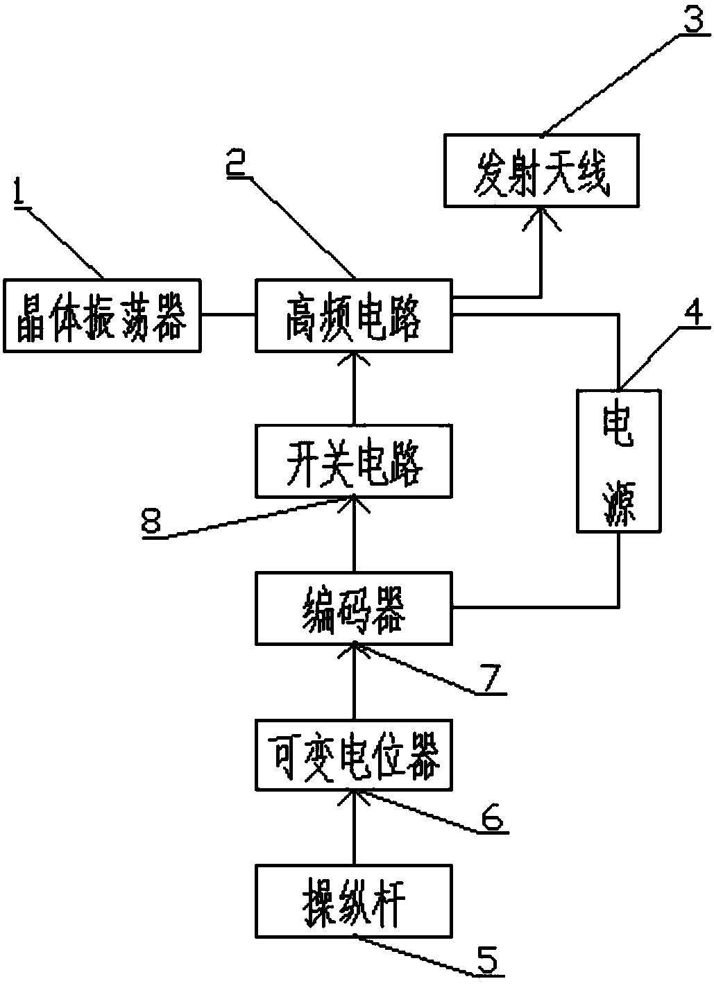
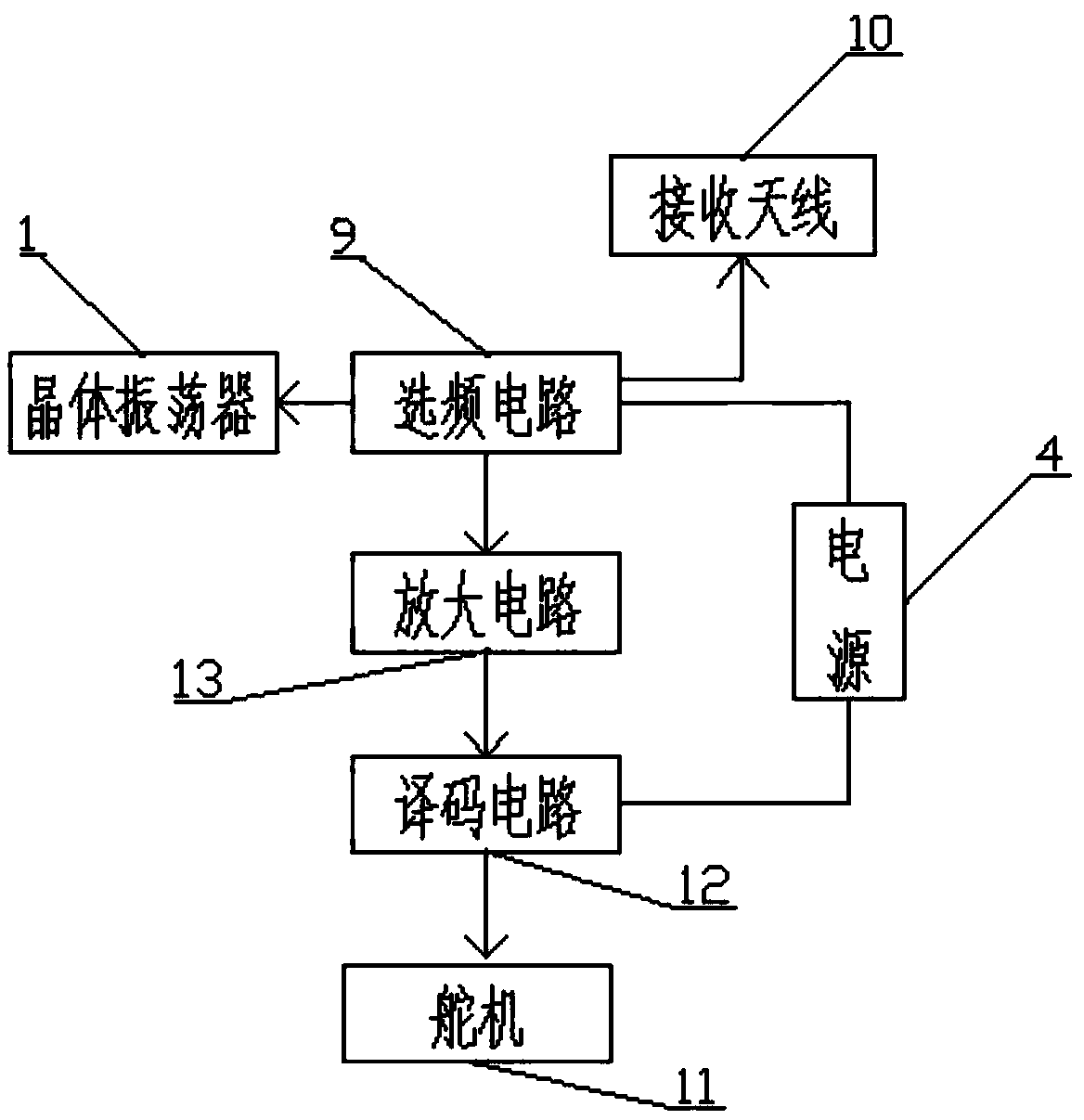
[0010] A model aircraft remote control system is mainly composed of a crystal oscillator 1, a high frequency circuit 2, a transmitting antenna 3, a power supply 4, a joystick 5, a variable potentiometer 6, an encoder 7, a switch circuit 8, a frequency selection circuit 9, Composed of receiving antenna 10, steering gear 11, decoding circuit 12 and amplifying circuit 13, it is characterized in that: joystick 5 is connected with variable potentiometer 6, and variable potentiometer 6 is connected with signal generator and encoder 7 connection, the signal generated by the encoder 7 is carried on the high-frequency circuit 2 through the switch circuit 8, the oscillation frequency is generated by the crystal oscillator 1, and finally sent out by the transmitting antenna 3. The receiving antenna 10 is connected with the frequency selection circuit 9, and the frequency selection circuit 9 is connected with the crystal oscillator 1 and the amplifier circuit 13, and the frequency selectio...
PUM
 Abstract
Description
Claims
Application Information