Gas-fired boiler based on porous medium combustion technology

A technology of porous media and combustion technology, applied in the field of gas boilers, can solve the problems of large volume, high emission, and low thermal efficiency, and achieve the effects of overcoming large volume, reducing combustion temperature, and compact device structure

Active Publication Date: 2017-01-04
河北泓碳能源技术有限公司
View PDF25 Cites 1 Cited by
  • Summary
  • Abstract
  • Description
  • Claims
  • Application Information

AI Technical Summary

Problems solved by technology

It overcomes the large volume, low thermal efficiency and NO x Disadvantages of high emissions

Method used


Image

  • Gas-fired boiler based on porous medium combustion technology
  • Gas-fired boiler based on porous medium combustion technology
  • Gas-fired boiler based on porous medium combustion technology

Examples


Embodiment 1

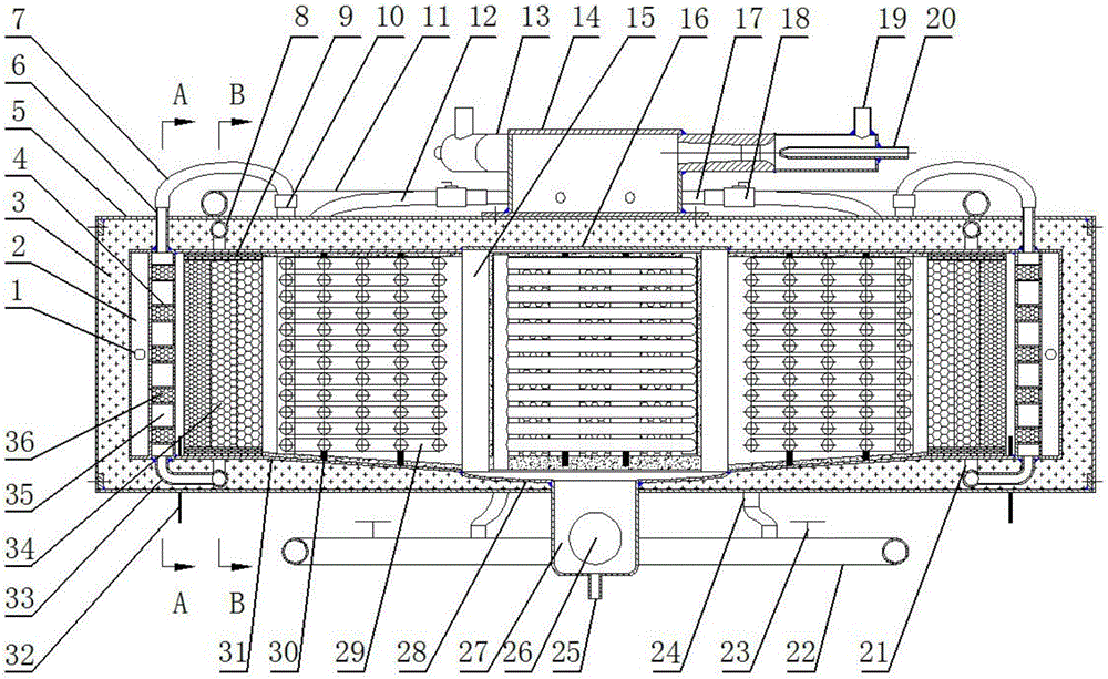
[0045] The structure and shape of the gas boiler based on porous media combustion technology in this embodiment are shown in Figure 1-4 .

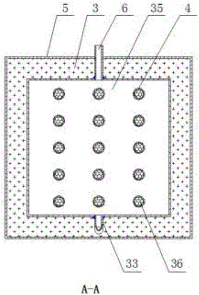
[0046] The gas boiler based on porous media combustion technology in this embodiment includes a premixer, a number of combustion heat exchange units and a connection box; the number of combustion heat exchange units are connected through the connection box, and the combustion heat exchange unit surrounds the connection box The body is symmetrically distributed in the center, and the connecting box and the combustion heat exchange unit are wrapped with a shell 5, and the insulation material 3 is filled between the shell 5 and the connecting box and the combustion heat exchange unit to prevent heat loss. The premixer is set at Connect the upper part of the box;

[0047] The combustion heat exchange unit includes an anti-backfire structure, a combustion chamber 40, a tail heat exchanger and an air intake chamber 2, and two premixed gas inle...

Embodiment 2

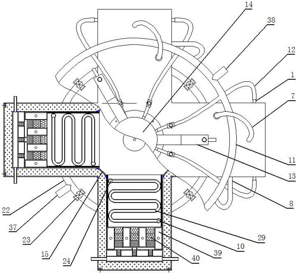
[0057] In this embodiment, the structural connections of the various parts of the gas boiler based on the porous media combustion technology are the same as in Embodiment 1, except that the premixer includes a gas nozzle 20, an injector 13, an air nozzle 19, a premix chamber 14 and a premixer. Mixed gas outlet pipe 17; the bottom of the premix chamber 14 is fixedly connected to the upper surface of the connecting box, and two injectors 13 are arranged on the side near the top of the premix chamber 14, between the two injectors 13 The included angle is 120°, and eight premixed gas outlet pipes 17 are evenly arranged on the side of the premixed chamber 14 near the bottom, and the premixed gas outlet pipes 17 are connected with the premixed gas in the intake chamber The inlet pipe 1 is connected, and each premixed gas connecting pipe 12 is equipped with a stop valve 18, which is convenient for adjusting the working load of the gas boiler based on the porous media combustion techno...

Embodiment 3

[0059] The structural connection of each part of the gas boiler based on the porous medium combustion technology in this embodiment is the same as that in Embodiment 1, the difference is that the gas boiler based on the porous medium combustion technology in this embodiment has 6 combustion heat exchange units, Figure 5 It is a top view cross-sectional schematic diagram of the connecting box. The cross-section in the figure shows the side plates 15 connecting the box. There are 6 side plates in total, and each side plate 15 is connected to every two combustion heat exchange units.

[0060] In the gas boiler based on the porous medium combustion technology of the present invention, the raw materials, parts and installation methods involved are all well known in the technical field.

[0061] What is not mentioned in the present invention is applicable to the prior art.


PUM


Abstract

The invention relates to a gas-fired boiler based on a porous medium combustion technology. The gas-fired boiler comprises a premixer, a number of combustion heat exchange units and a connecting box. The combustion heat exchange units are connected through the connecting box. The combustion heat exchange units are distributed around the connecting box in central symmetry. The connecting box and the combustion heat exchange units are wrapped by a shell. The position between the shell and the connecting box and combustion heat exchange units is filled with a heat preservation material. The premixer is arranged on the upper portion of the connecting box. Each combustion heat exchange unit comprises an anti-backfire structure, a combustion chamber, a tail heat exchanger and a gas inlet chamber, and two premixed gas inlet pipes are welded to the side wall face of each gas inlet chamber. Each anti-backfire structure is composed of an anti-backfire water chamber and an anti-backfire gas inlet channel. Each anti-backfire gas inlet channel is embedded into the corresponding anti-backfire water chamber through welding. The front end of each anti-backfire water chamber is connected with the corresponding gas inlet chamber. The rear end of each anti-backfire water chamber is connected with the corresponding combustion chamber. Each tail heat exchanger is arranged at an outlet of the corresponding combustion chamber.

Description

technical field [0001] The invention relates to the technical field of water heaters which surround a combustion chamber with a water exchange chamber and realize waste heat recovery through a heat exchange device, in particular to a gas boiler based on porous medium combustion technology. Background technique [0002] With the optimization and adjustment of my country's energy structure, gas-fired boilers have attracted much attention because of their economical, efficient and environmentally friendly features. However, countries all over the world have put forward higher requirements on energy utilization efficiency and environmental pollutant discharge. The existing gas-fired boilers have low thermal efficiency and high pollutant discharge. In order to improve the efficiency of the boiler, the existing technology is to increase the heat exchange area or increase the waste heat recovery device, which makes the structure of the boiler more complicated and the volume larger....

Claims


Application Information

Patent Timeline
Patent Type & Authority Applications(China)
IPC IPC(8): F24H1/44F24H9/18F24H9/00
CPCF24H1/44F24H9/0005F24H9/1836
Inventor 王恩宇沈家利苟湘吴晋湘刘联胜
Owner 河北泓碳能源技术有限公司
Why Eureka
Try Eureka