Vacuum debugging process for light cavity of high-power gas laser

A gas laser, high-power technology, used in lasers, laser parts, phonon exciters, etc., can solve the problems of optical cavity deformation, reduced position accuracy, difficult optical cavity adjustment, etc., to achieve stable laser output power and achieve High-precision adjustment, precise effect of optical cavity adjustment

Active Publication Date: 2011-07-06
NINGBO SIASUN ROBOT TECH CO LTD
View PDF0 Cites 4 Cited by
  • Summary
  • Abstract
  • Description
  • Claims
  • Application Information

AI Technical Summary

Problems solved by technology

[0003] At present, the optical cavity adjustment technology of domestic high-power gas lasers has the following problems: First, the optical cavity adjustment uses the red light of a low-power semiconductor laser as the adjustment indicator light, but its spot diameter is large, and high-precision adjustment cannot be achieved ;Secondly, the adjustment of the optical cavity is mostly carried out under standard atmospheric pressure, while the high-power gas laser works in a vacuum state. Due to the pressure change, the cabinet will be deformed, causing the change of the optical cavity reference and reducing the position accuracy of the optical cavity. ; Third, during the working process of the laser, the optical cavity will be deformed due to external force, which will cause the reduction of position accuracy
Therefore, if the optical cavity has no reference for adjustment, it will not be able to return to its original position during the laser output process, which will not only greatly reduce the quality and energy of the output laser beam, but also make subsequent optical cavity adjustments difficult

Method used


Image

  • Vacuum debugging process for light cavity of high-power gas laser
  • Vacuum debugging process for light cavity of high-power gas laser
  • Vacuum debugging process for light cavity of high-power gas laser

Examples


Embodiment 1

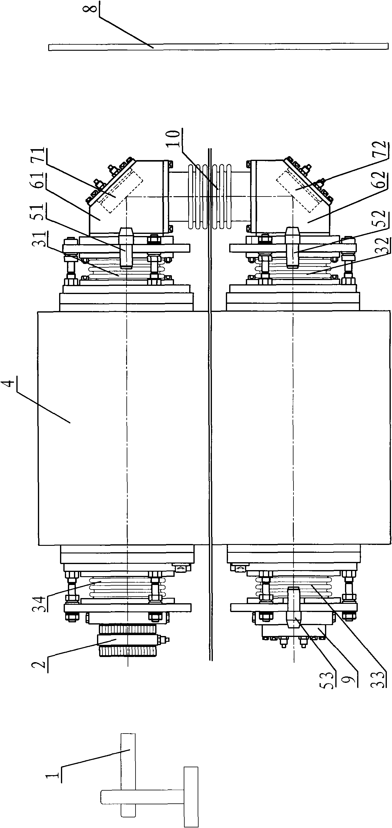
[0038] Embodiment 1: The optical system used in this example is a U-shaped folded optical cavity structure, refer to figure 1 , including a laser box 4, a front window mirror module 2, a rear mirror module 9, turning mirror mounts 61, 62, turning mirrors 71, 72, optical axis monitoring systems 51, 52, 53, a telescope 1 and a receiving screen 8, the front The window mirror module 2 is arranged on one side of the laser box 4 through the angle adjustment module 34, and the rear mirror module 9 is on the same side as the front window mirror module 2, and is arranged on the laser box through the angle adjustment module 33 with the optical axis monitoring system 53 4, there are two turning mirror mirror mounts 61, 62, which are respectively arranged on the other side of the laser box 4 through angle adjustment modules 31, 32 with optical axis monitoring systems 51, 52, and turning mirrors 71, 72 are respectively set On the turning mirror mirror bases 61, 62, during debugging, the te...

Embodiment 2

[0057] Embodiment 2: The optical system of this example is a single cavity structure, refer to Figure 6 , including a laser cabinet 4, a front window mirror module 2, a rear mirror module 9, an optical axis monitoring system 5, an inner focusing telescope 1 and a receiving screen 8, and the front window mirror module 2 is arranged on the laser cabinet 4 through an angle adjustment module 34 The rear mirror module 9 is arranged on the other side of the laser box 4 through the angle adjustment module 33 with the optical axis monitoring system 53. When debugging, the telescope 1 is located at the installation port side of the front window mirror module 2, and The distance between the installation port of the front window mirror module 2 is 1.5-3 meters, and the receiving screen 8 is located on the other side of the laser box 4 .

[0058] The structures of the angle adjustment module 34 and the optical axis monitoring system 53 in this example are the same as those in the first e...

Embodiment 3

[0069] Embodiment 3: The optical system of this example is a V-shaped cavity structure, refer to Figure 7, including a laser box 4, a front window mirror module 2, a rear mirror module 9, a turning mirror 7, an optical axis monitoring system 51, 53, a telescope 1 and a receiving screen 8, and the front window mirror module 2 is arranged on the laser through an angle adjustment module 34 On one side of the box body 4, the rear mirror module 9 is on the same side as the front window mirror module, and is arranged on the laser box body 4 through the angle adjustment module 33 with the optical axis monitoring system 53, and the turning mirror 7 passes through the camera with the monitoring system 51. The angle adjustment module 31 is arranged on the other side of the laser box body 4, and the axes of the turning mirror 7, the front window mirror module 2 and the rear mirror module 9 form a V shape. On the mouth side, the distance from the installation port of the front window mir...


PUM


Abstract

The invention discloses a vacuum debugging process for a light cavity of a high-power gas laser, which comprises the following steps of: fixing and adjustment of a telescope: cross scale marks in the telescope and mounting ports at two sides of a box body corresponding to the cross scale marks are arranged coaxially; preliminary adjustment of the light cavity: an angle adjusting module is adjusted to enable the cross scale marks of the telescope before and after reflection of each optical lens to be overlapped, and the angle variation of each optical lens is monitored through an optical axis monitoring system; vacuum correction of the light cavity: a laser box body adjusts the corresponding variation generated by each monitoring system in a vacuum condition and the overlap ratio according to the horizontal overlapping condition of the cross scale marks of the telescope, and the laser box body adjusts the angle adjusting modules of a front window lens module under a standard air pressure to enable the images of cross scale marks of the telescope before and after reflection to be overlapped; and online correction of the light cavity: in the light emitting process, all the angle adjusting modules are adjusted according to the angle variation of each monitoring system on a receiving screen to recover the position of a light spot of the optical axis monitoring system before light emission. The vacuum debugging process can realize real-time monitoring and correction.

Description

technical field [0001] The invention belongs to the technical field of optical cavity adjustment of gas lasers, in particular to an optical cavity vacuum adjustment process of high-power gas lasers. Background technique [0002] In the manufacturing process of industrial high-power gas lasers, the adjustment accuracy of the initial optical cavity not only affects the output power of the laser, but also affects the stability of the laser beam direction. Therefore, it is required to achieve high-precision adjustment of the laser optical cavity before emitting light. [0003] At present, the optical cavity adjustment technology of domestic high-power gas lasers has the following problems: First, the optical cavity adjustment uses the red light of a low-power semiconductor laser as the adjustment indicator light, but its spot diameter is large, and high-precision adjustment cannot be achieved ;Secondly, the adjustment of the optical cavity is mostly carried out under standard at...

Claims


Application Information

Patent Timeline
Patent Type & Authority Applications(China)
IPC IPC(8): H01S3/086H01S3/08H01S3/22
Inventor 邢飞贾吉庆宫铭辉刘佳
Owner NINGBO SIASUN ROBOT TECH CO LTD
Why Eureka
Try Eureka