Plug-in machine with plug-in fixing function

A fixed-function, plug-in machine technology, applied in the direction of electrical components, electrical components, etc., can solve the problems of increasing the scrap rate of PCB circuit boards, affecting the normal operation of the plug-in machine, reducing the production efficiency of the plug-in machine, etc., to achieve strong practicability and avoid The effect of beating and reducing the scrap rate

Inactive Publication Date: 2011-07-06
DONGGUAN SCIENCGO MACHINERY MFG
View PDF5 Cites 24 Cited by
  • Summary
  • Abstract
  • Description
  • Claims
  • Application Information

AI Technical Summary

Benefits of technology

In this new design for an electrical connector used in computer systems, there has been developed a way to fix electronics during plugging process without causing damage or separating them from the printed wiring board (PCB).

Problems solved by technology

This patented problem addressed during this patents describes how current plugs used for inserting electrical devices have issues when they move around inside the holes formed through printed circuits (PC). These movements cause them to come off their own legs and become bent over time causing damage to other parts within the system. Existing solutions involve adding extra hardware like stops at specific locations along the edges where the electric component's leg goes under it, but these methods may also lead to incorrect placements caused by shaking or misalignment between different layers of materials.

Method used


Image

  • Plug-in machine with plug-in fixing function
  • Plug-in machine with plug-in fixing function
  • Plug-in machine with plug-in fixing function

Examples


Embodiment Construction

[0029] In order to facilitate the understanding of those skilled in the art, the present invention will be further described below in conjunction with the embodiments and accompanying drawings, and the content mentioned in this embodiment is not intended to limit the present invention.

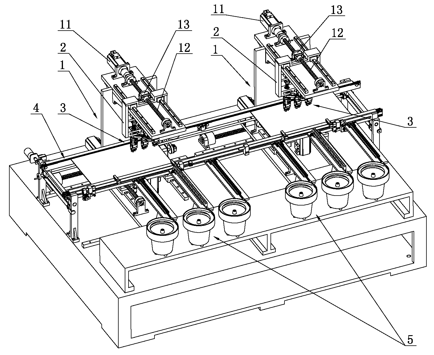
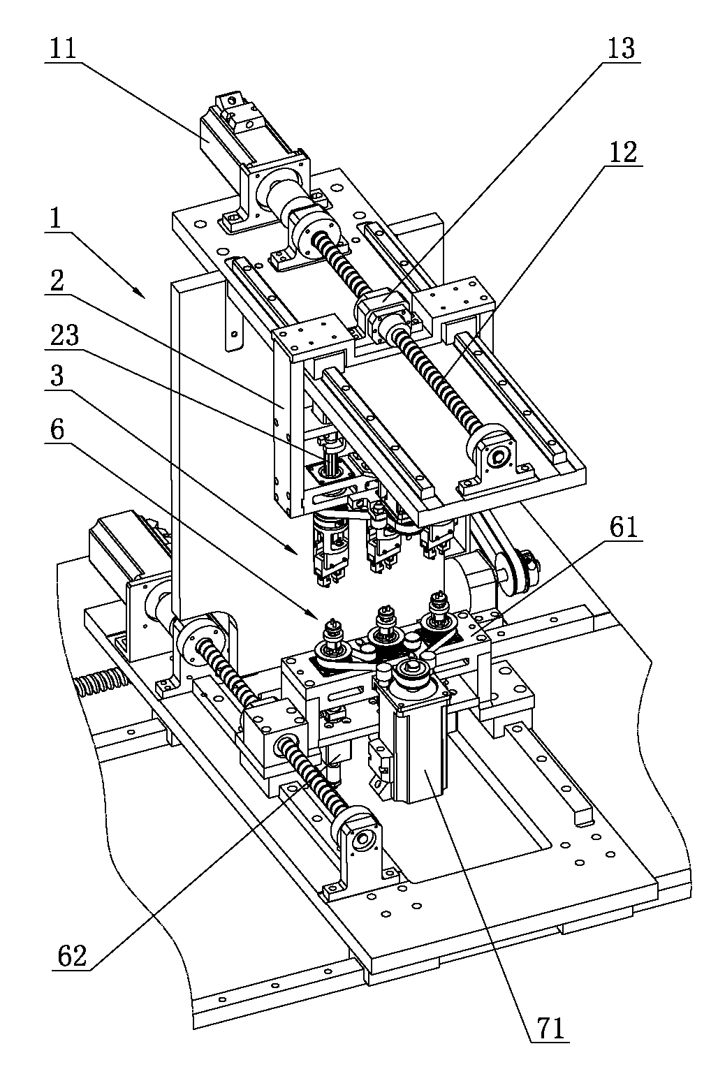
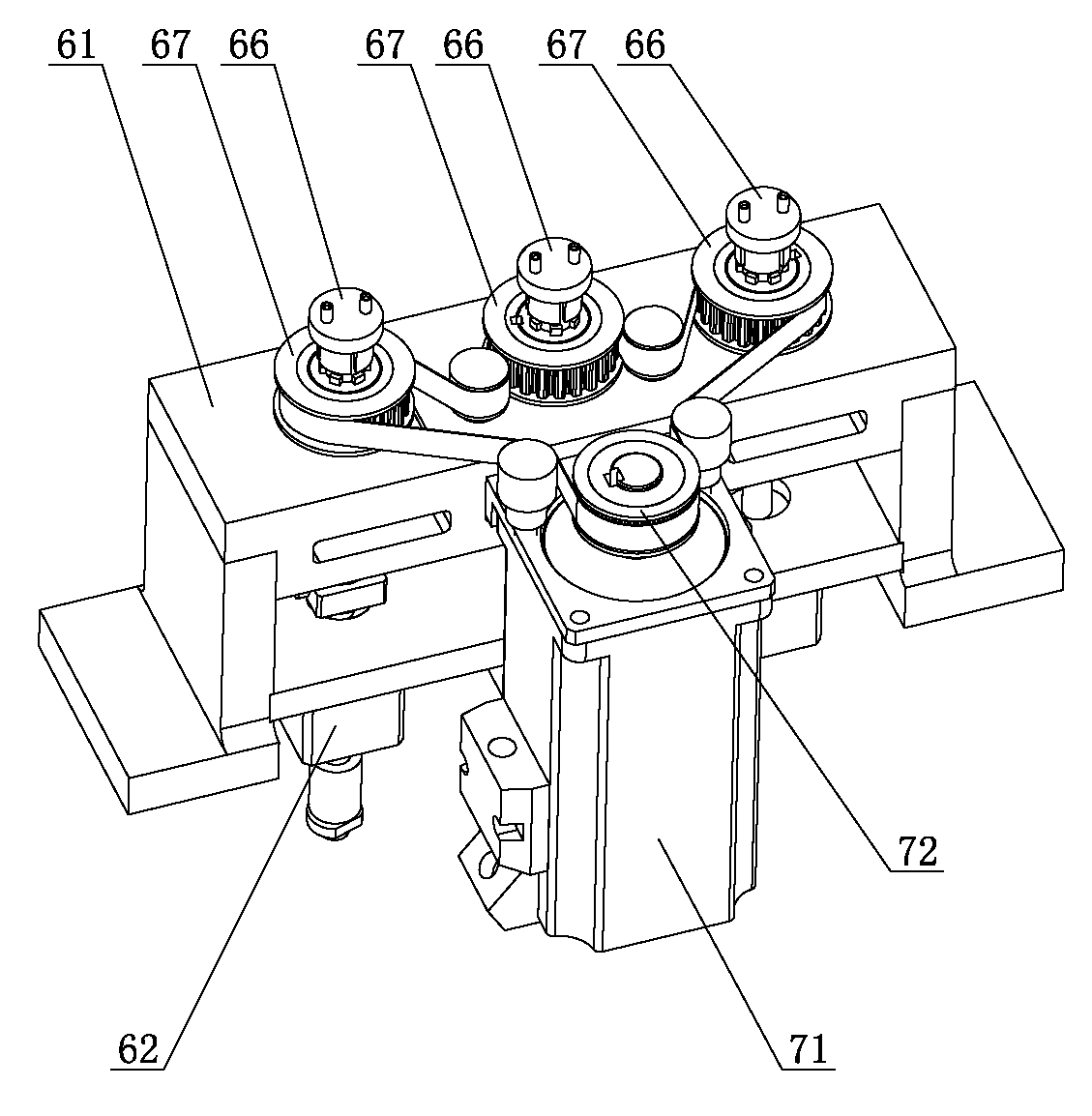
[0030] Such as Figure 1 to Figure 5 ,and Figure 8 to Figure 11 A plug-in machine with a plug-in fixing function shown includes a machine tool, a frame 1 that is movably arranged on the machine tool, a movable frame 2 that is movably arranged on the frame 1, a material clamping claw 3 that is arranged on the movable frame 2, and a The plate transport track 4 of the frame 1 and the first driving mechanism that drives the material clamping claw 3 to move longitudinally, the frame 1 is equipped with a feeder 5, and the frame 1 is provided with a bent foot fixing device 6, the bent foot The fixing device 6 includes a base body 61, a bending mechanism arranged on the base body 61, a second drivin...


PUM


Abstract

The invention relates to the technical field of electronic component plug-in machines, in particular to a plug-in machine with plug-in fixing function. The plug-in machine comprises a machine tool, racks, movable racks, material clamping paws, plate transporting rails and a first driving mechanism, wherein the racks are provided with bend fixing devices; each bend fixing device comprises a base body, a buckling mechanism, a second driving mechanism and a first pressure cylinder; the buckling mechanism comprises bearings and internal spline sleeves; the internal spline sleeves are movably sleeved with external spline shafts; bend heads are arranged at the upper ends of the external spline shafts; the external spline shafts are provided with rotation wheels; the second driving mechanism is connected with the rotation wheels in a transmission manner; the first pressure cylinder is connected with the external spline shafts; steering spline sleeves and steering motors are movably sleeved on the movable racks; and down plug pressure cylinders are installed on the movable racks. The technical scheme has the following advantages: the electronic components are avoided from jittering on the PCB, thus reducing the phenomenon that the plugged electronic components break away from the PCB and ensuring normal operation of the equipment; and the practicability is strong.

Description


Claims


Application Information

Patent Timeline
Owner DONGGUAN SCIENCGO MACHINERY MFG
Why Eureka
Try Eureka