Stamping die production structure

A production structure, stamping die technology, applied in the direction of manufacturing tools, grinding machines, metal processing equipment, etc., can solve problems such as unfavorable use, affecting the removal of the mold, and damage to the surface of the mold, so as to increase the air circulation speed, avoid excessive temperature, avoid affect the effect of processing

Inactive Publication Date: 2020-10-30
孝感德客电子科技有限公司
View PDF10 Cites 4 Cited by
  • Summary
  • Abstract
  • Description
  • Claims
  • Application Information

AI Technical Summary

Problems solved by technology

[0002] Molds are various molds and tools used in industrial production for injection molding, blow molding, extrusion, die-casting, forging, smelting, stamping and other methods to obtain the required products. Composed of various parts, different molds are composed of different parts. Stamping dies are a special process equipment for processing materials (metal or non-metal) into parts (or semi-finished products) in cold stamping processing, while stamping dies are used in production. Usually, various processes such as drawing review, material preparation, blank processing, formwork processing, core processing, electrode processing, mold part processing, inspection, assembly, flying mold, etc. are required. Each process needs to use one or more corresponding The operation of equipment, devices, tooling, etc., including grinding and polishing, grinding and polishing is mainly to remove burrs from the surface of various parts of the stamping die, such as the upper template, the lower template, etc., so that the surface is smooth and bright, which belongs to stamping The necessary production structure for mold processing; however, the existing production structure of stamping dies does not have the function of collecting chips. When grinding and polishing, the surface of the mold will be worn and scraps will be generated. If the scraps are not recycled in time, they will It will lead to messy work place, and it will also cause damage to the surface of the mold caused by the splash of waste materials. The use effect is poor, and secondly, it does not have the function of cooling. High affects people to take out the mold after grinding, which is not conducive to use

Method used

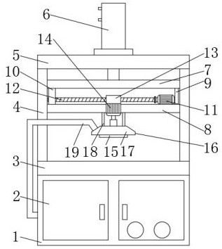
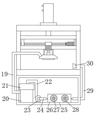
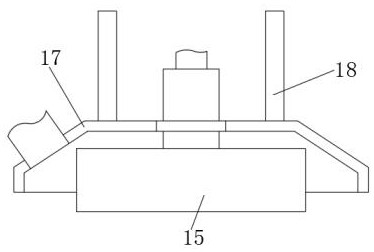

Image

  • Stamping die production structure
  • Stamping die production structure
  • Stamping die production structure

Examples


Embodiment Construction

[0021] In order to make the technical means, creative features, objectives and effects achieved by the present invention easy to understand, the present invention will be further explained below in conjunction with specific embodiments.

[0022] In the description of the present invention, it should be noted that the terms "upper", "lower", "inner", "outer", "front end", "rear end", "both ends", "one end", "the other end" The orientation or positional relationship of other indications is based on the orientation or positional relationship shown in the drawings, which is only for the convenience of describing the present invention and simplifying the description, rather than indicating or implying that the pointed device or element must have a specific orientation and The azimuth structure and operation cannot be understood as a limitation of the present invention. In addition, the terms "first" and "second" are only used for descriptive purposes, and cannot be understood as indic...


PUM


Abstract

The invention discloses a stamping die production structure. The stamping die production structure comprises a supporting box, a movable door is movably installed on the front portion of the supporting box, a machining table is fixedly installed on the upper portion of the supporting box, a portal frame is fixedly installed on the upper portion of the machining table, a top plate is fixedly installed on the top of the portal frame, an air cylinder is fixedly installed in the middle position of the upper portion of the top plate, a first cantilever and a second cantilever are slidably connectedinto the portal frame, the first cantilever is located above the second cantilever, a first connecting column and a second connecting column are fixedly connected to the two ends between the first cantilever and the second cantilever, and a driving motor is fixedly installed at a position, close to one end, of the upper part of the second cantilever. According to the stamping die production structure, waste chips generated during grinding machining can be collected, machining is prevented from being influenced by the waste chips, a ground die can be cooled as well, the phenomenon that takingout of the die is influenced due to the fact that the temperature is too high is avoided, and use is more facilitated.

Description

Technical field [0001] The invention relates to the field of mold production, in particular to a stamping mold production structure. Background technique [0002] Molds are various molds and tools used in industrial production to obtain the required products by injection molding, blow molding, extrusion, die-casting, forging, smelting, stamping and other methods. It is a tool used to make molded articles. It is composed of various parts, and different molds are composed of different parts. In cold stamping processing, stamping dies are a special process equipment for processing materials (metal or non-metal) into parts (or semi-finished products). It usually requires multiple processes such as drawing review, material preparation, blank processing, mold base processing, mold core processing, electrode processing, mold parts processing, inspection, assembly, flying molds, etc. Each process needs to use one or more corresponding processes Equipment, equipment, tooling, etc., inclu...

Claims


Application Information

Patent Timeline
Patent Type & Authority Applications(China)
IPC IPC(8): B24B19/20B24B55/12B24B55/02
CPCB24B19/20B24B55/02B24B55/12
Inventor 祝茜
Owner 孝感德客电子科技有限公司
Why Eureka
Try Eureka