Camshaft adjustment device for an internal combustion engine

一种凸轮轴调节、调节装置的技术,应用在阀装置、机械设备、发动机元件等方向,能够解决动力变差、提高制造成本、关闭等问题,达到避免控制装置、短反应时间的效果

Inactive Publication Date: 2011-07-06
SCHAEFFLER TECH AG & CO KG
View PDF11 Cites 4 Cited by
  • Summary
  • Abstract
  • Description
  • Claims
  • Application Information

AI Technical Summary

Problems solved by technology

[0006] The disadvantage of this embodiment is that opening and closing the shut-off valve for temperature control requires additional control means, which increases manufacturing costs
[0007] A further disadvantage of this arrangement is the thermostatic closure of the shut-off valve and the bypass at high pressurized oil temperatures and high pressurized oil inlet pressures
During high-speed engine operation, the pressurized oil supply via the non-return valve therefore takes place with high flow resistance and a choked pressurized oil flow, whereby the dynamics of the control process are significantly reduced
[0008] In addition, when pressurized oil is loaded in the operating state at low pressure oil temperature with the shut-off valve open, the operation causes the excess pressure that occurs in the pressure chamber to be carried over via the open bypass and causes the pressure oil to flow to the pressure oil pump or to the pressure oil Backflow of the reserve container, with the consequence of a similarly worsened regulation dynamics

Method used


Image

  • Camshaft adjustment device for an internal combustion engine
  • Camshaft adjustment device for an internal combustion engine
  • Camshaft adjustment device for an internal combustion engine

Examples


Embodiment Construction

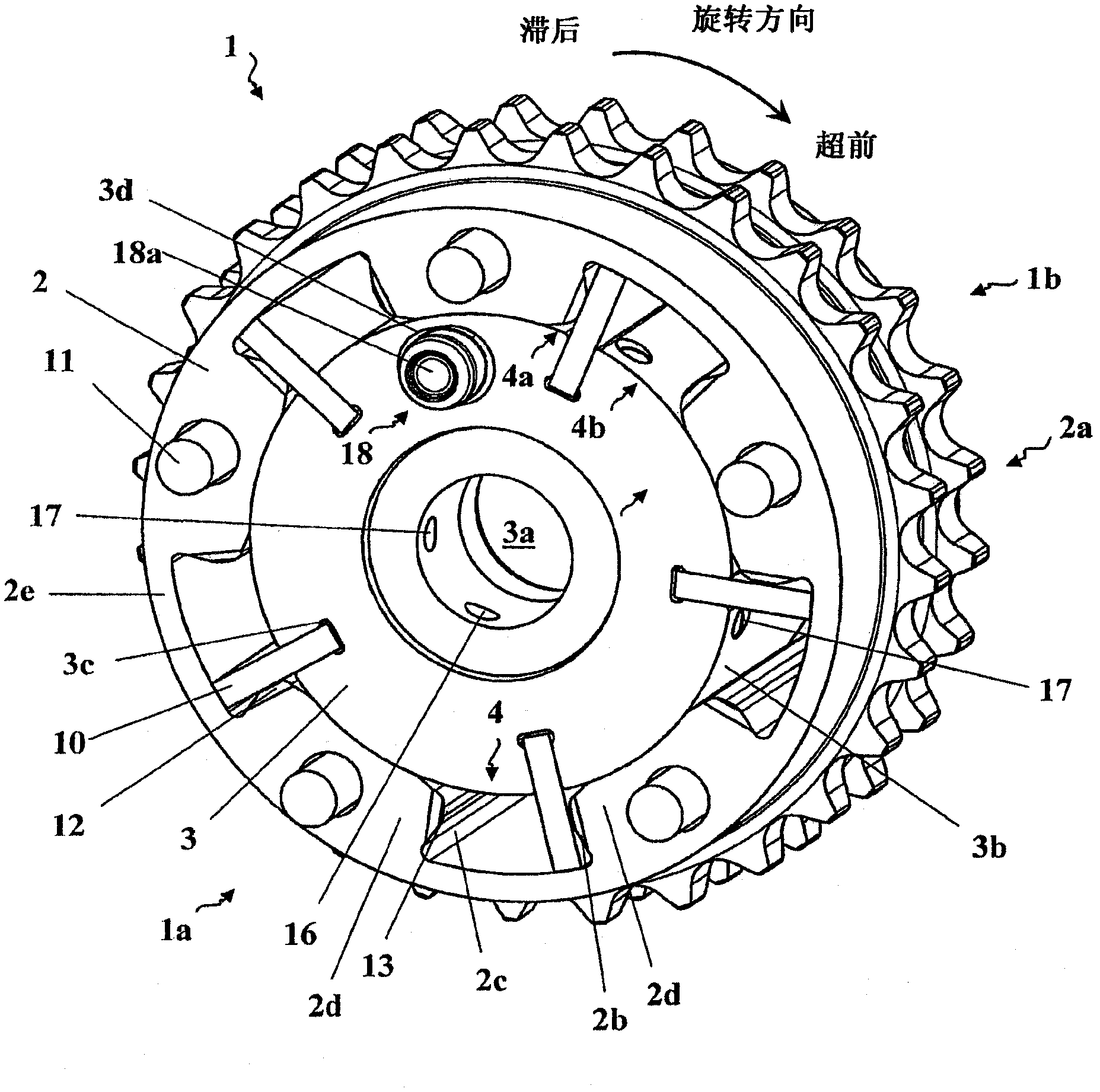
[0022] figure 1 The hydraulic camshaft adjusting device 1 is shown in a perspective view without the front cover on the side 1a facing away from the engine. The camshaft adjusting device 1 has a transmission wheel 2 mounted on an output element 3 so that it can rotate therewith. The transmission wheel drives the illustrated sprocket connected to the transmission wheel 2 via the meshing portion 2a, and its meshing teeth can mesh with a chain driven by a crankshaft not shown. However, it is also conceivable that the transmission wheel 2 is driven by a belt or a gear. The driven part 3 is designed as an impeller and is connected to a camshaft (not shown) in a rotationally fixed manner via a central receptacle 3 a, for example by means of screws or welding. Five vanes 10 that are symmetrically distributed on the circumference and extend radially are formed on the driven member 3 . Proceeding from the outer circumference 3 b , the driven element 3 has axially running vane groove...


PUM


Abstract

The invention relates to a camshaft adjustment device (1) having a pinion (2) and a drive part (3) that is disposed in a pivoting manner relative thereto, wherein the pinion (2) and the drive part (3) are operatively connected to each other via at least one pressure chamber (4) that can be pressurized by means of a pressure means, and wherein at least one regulating device (5) is provided for regulating the pressure means supply to the pressure chamber (4) and the pressure means discharge from the pressure chamber (4), wherein to supply the pressure means at least one pressure means supply connection (6) is configured between the regulating device (5) and a pressure means supply device (7), characterized in that the passage of the pressure means can be blocked in the pressure means supply connection (6) in the direction of the pressure means supply device (7); by means of at least two check valves (8, 9) that are switched in parallel to each other.

Description

technical field [0001] The invention relates to a camshaft adjusting device with a drive wheel and a driven part which can be arranged to rotate relative to the drive wheel, wherein the drive wheel and the driven part are operatively connected via at least one pressure chamber to which pressurized oil can be applied, and At least one regulating device is provided for regulating the supply of pressurized oil to the pressure chamber and the discharge of pressurized oil from the pressure chamber, wherein at least one pressure oil supply connection is formed between the regulating device and the pressurized oil supply device for the pressurized oil supply. Background technique [0002] Camshaft adjusting devices of this type are known from DE 101 03 876 A1, US 6.553.951 B2 and US 2006 / 0213471 A1. There, the housing part, which can be driven by the motor of the internal combustion engine, and the rotary part, which is connected in a rotationally fixed manner to the camshaft of th...

Claims


Application Information

Patent Timeline
Patent Type & Authority Applications(China)
IPC IPC(8): F01L1/344
CPCF01L1/344F01L1/3442
Inventor 米夏埃尔·布塞卢茨·维特赫夫特
Owner SCHAEFFLER TECH AG & CO KG
Why Eureka
Try Eureka