Total-flooding jet polishing device and method

A polishing device and fully submerged technology, which is applied in the direction of abrasive jet machine tools, abrasives, metal processing equipment, etc., to achieve the effects of reducing the difficulty of system polishing control, simple structure, and cost reduction

Inactive Publication Date: 2011-07-13
INST OF OPTICS & ELECTRONICS - CHINESE ACAD OF SCI
View PDF5 Cites 36 Cited by
  • Summary
  • Abstract
  • Description
  • Claims
  • Application Information

AI Technical Summary

Problems solved by technology

[0005] Aiming at the shortcomings of existing jet polishing devices and polishing methods, the purpose of the present invention

Method used


Image

  • Total-flooding jet polishing device and method
  • Total-flooding jet polishing device and method
  • Total-flooding jet polishing device and method

Examples


Embodiment 1

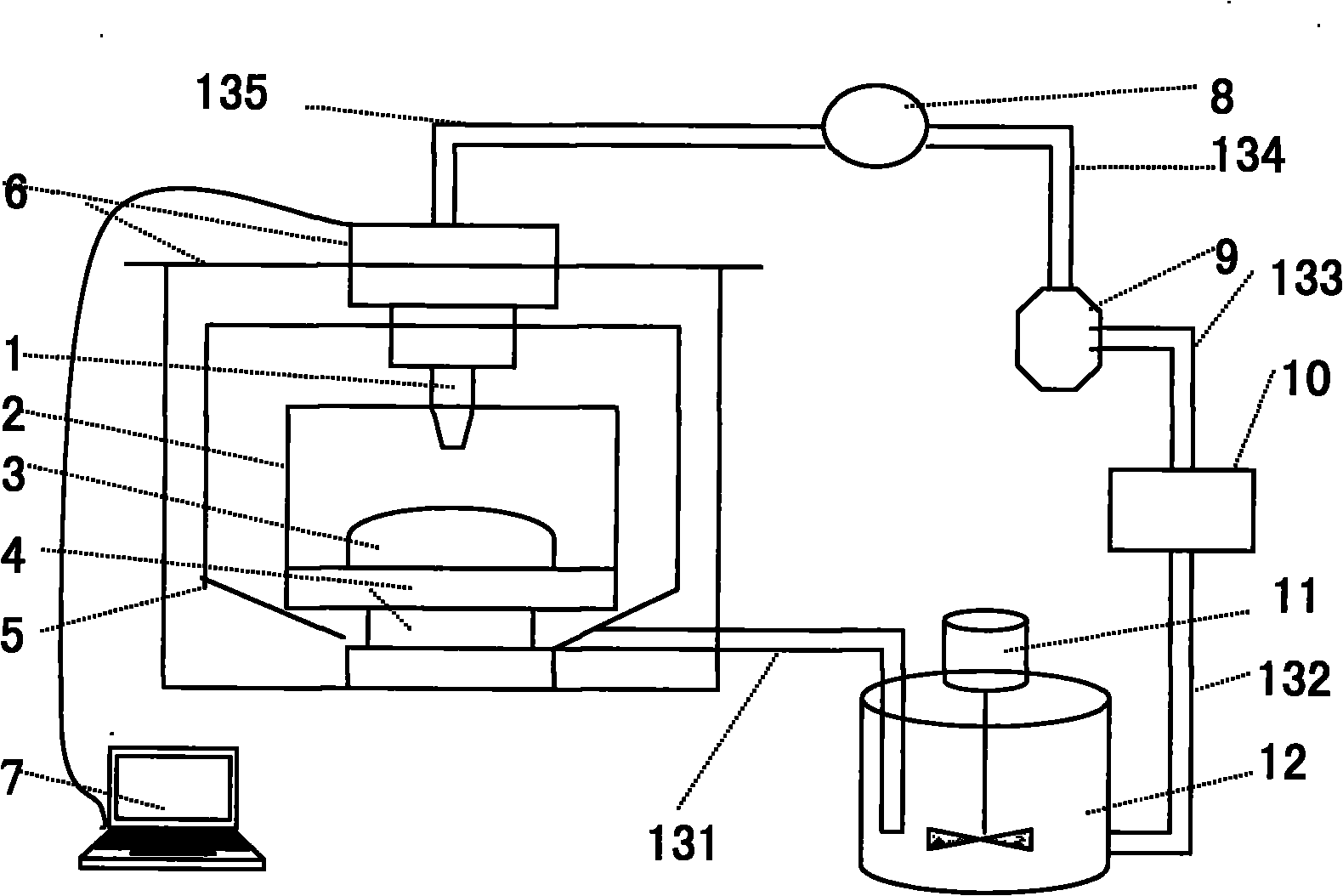
[0022] Example 1: Combining figure 1 The fully submerged jet device system describes this embodiment. This embodiment includes a nozzle 1, a polishing liquid container 2, a workpiece to be polished 3, a workpiece clamping 4, a polishing liquid recovery tank 5, a numerically controlled polishing machine tool 6, a numerically controlled computer 7, and a pressure gauge 8 , a pressure regulating valve 9, a booster pump 10, a polishing liquid agitator 11, a polishing liquid recovery container 12 and several liquid pipelines 131 to 135. The polishing liquid recovery tank 5 is fixed on the workpiece table of the CNC polishing machine tool 6; the polishing liquid container 2 is fixed on the polishing liquid recovery tank 5; One end of the nozzle 1 is fixed in the polishing head of the CNC polishing machine 6, and the other end of the nozzle 1 is connected to one end of the fifth liquid pipeline 135; the two ports of the pressure gauge 8 are respectively fixed with the first The othe...

Embodiment 2

[0024] Embodiment 2: Combination figure 1To illustrate this embodiment, the CNC machine tool and the CNC system of this embodiment use the CCOS800mm polishing machine tool and CNC system developed by the Institute of Optoelectronics, Chinese Academy of Sciences. The nozzle 1 is a cylindrical nozzle, and the nozzle 1 is a cylindrical nozzle of the LECHLER brand. On the polishing head of machine tool 6, under the instruction of numerical control computer 7, nozzle 1 can realize the motion of X, Y, Z three directions, and the booster pump 10 of this embodiment can select the VA10 model diaphragm pump of German Verder Company for use, this The polishing liquid recovery part of the embodiment includes a polishing liquid recovery container 12 and a polishing liquid agitator 11, and the polishing liquid agitator 11 can be realized by using a conventional motor equipped with stirring blades. The polishing liquid agitator 11 is located in the polishing liquid recovery container 12 for ...

Embodiment 3

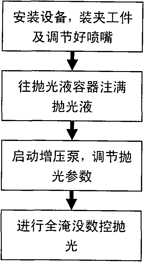
[0025] Example Three: Combining figure 1 and image 3 Describe this embodiment, this embodiment is realized through the following steps:

[0026] Step S1: After fixing each component according to the specific embodiment 1, the workpiece 3 to be polished is clamped in the polishing liquid container 2 through the workpiece clamping 4, and the workpiece clamping 4 is adjusted so that the topmost distance of the workpiece 3 to be polished is away from the polishing solution. The top of the liquid container 2 is 30-60 mm, and the numerical control computer 7 adjusts the coordinate position of the nozzle 1 on the numerical control polishing machine tool 6, so that the distance between the outlet of the nozzle 1 and a certain polishing point on the surface of the workpiece is controlled within 5 times to 6 mm of the outlet diameter of the nozzle 1 about times;

[0027] Step S2: inject the polishing liquid into the polishing liquid container 2 until the polishing liquid container 2 ...


PUM


Abstract

The invention discloses a total-flooding jet polishing device and method. The device comprises a nozzle, a polishing solution container, a workpiece to be polished, a workpiece clamp, a polishing solution recovery tank, a numerical control polishing machine tool, a numerical control computer, a pressure gage, a pressure regulating valve, a booster pump, a polishing solution stirrer, a polishing solution receptacle and a plurality of liquid pipelines, wherein the workpiece clamp is fixed on the bottom end of the polishing solution container; the workpiece to be polished is arranged in and fixedly connected with the workpiece clamp; one end of the nozzle is fixed in the polishing moving head of the numerical control polishing machine tool; and the coordinate position and the dwell time of the nozzle are controlled by the numerical control computer to remove the material of the workpiece at fixed quantity. The method comprises the following steps: clamping the workpiece to be polished inthe polishing solution container; injecting the polishing solution into the polishing solution container until the workpiece to be polished and the outlet of the nozzle are completely flooded in the polishing solution; starting a hydraulic part to start flooding jet polishing; regulating distance between the nozzle and the workpiece to be polished by the numerical control computer; and controlling polishing dwell time to remove materials at fixed quantity.

Description

technical field [0001] The invention belongs to the technical field of photoetching objective lens optical manufacturing, and relates to a novel jet polishing device and a polishing method. Background technique [0002] The key equipment for microelectronics is an important support for microelectronics technology. The lithography objective lens is the key core part of the distributed and repeated projection lithography of special equipment for microelectronics. direct relation. The quality requirements of lithography objective optical components are an order of magnitude higher than other high-precision optical components. For example, the radius of curvature is less than or equal to 1 μm, the surface error is less than or equal to λ / 20~λ / 100, and the rms root mean square value is less than or equal to It is equal to λ / 100~λ / 300, etc., and puts forward extremely strict requirements on the accuracy of the outer diameter, center thickness, radius of curvature, damage layer, e...

Claims


Application Information

Patent Timeline
IPC IPC(8): B24C3/00B24C1/08
Inventor 施春燕袁家虎伍凡万勇建范斌雷柏平
Owner INST OF OPTICS & ELECTRONICS - CHINESE ACAD OF SCI
Why Eureka
Try Eureka