Light emitting diode lamp tube and liquid crystal display device

A liquid crystal display device and light-emitting diode technology, which is applied to semiconductor devices of light-emitting elements, lighting devices, components of lighting devices, etc., can solve the problems of temperature rise of transistors, uneven brightness, and darkening of backlight area 211.

Inactive Publication Date: 2011-07-13
TPV ELECTRONICS (FUJIAN) CO LTD
View PDF6 Cites 6 Cited by
  • Summary
  • Abstract
  • Description
  • Claims
  • Application Information

AI Technical Summary

Problems solved by technology

[0009] Therefore, the driving circuit 22 needs to have a current sharing function to solve the above-mentioned problem of uneven brightness, but this will lead to an increase in the cost of the driving circuit 22
[0010] If the driving circuit 22 has a current sharing function but does not have a short-circuit protection function, when any one of the light-emitting diodes 131 is short-circuited due to damage, the operating voltage of the light-emitting unit 13 to which the light-emitting diode 131 belongs will be reduced. decrease, causing the drive circuit 22 to increase the voltage of the feedback control terminal 222 electrically connected to the light emitting unit 13, and the feedback control terminal 222 is usually connected to the drain of the transistor of the current equalizing circuit (not shown) inside the drive circuit 22 (drain) or collector (collector) are electrically connected, so that the temperature of the transistor of the current sharing circuit of the drive circuit 22 rises due to the increase in power consumption
[0011] Therefore, the driving circuit 22 needs to have a short-circuit protection function to avoid damage due to overheating of the transistors in the current sharing circuit, but this will further increase the cost of the driving circuit 22
[0012] In addition, assuming that at least one light-emitting diode 131 in the light-emitting unit 13 corresponding to the backlight area 211 is short-circuited due to damage, causing the drive circuit 22 to activate the short-circuit protection function and turn off the light-emitting unit 13 corresponding to the backlight area 211 (that is, at this time the corresponding backlight The light-emitting unit 13 in the area 211 is turned off and does not emit light), then compared with the backlight areas 212~214, the backlight area 211 will be seriously dark
[0013] If any one of the light emitting diodes 131 is open due to damage, the other light emitting diodes 131 connected in series with the light emitting diode 131 will not work either, causing the light emitting unit 13 to which they belong to not to emit light.

Method used


Image

  • Light emitting diode lamp tube and liquid crystal display device
  • Light emitting diode lamp tube and liquid crystal display device
  • Light emitting diode lamp tube and liquid crystal display device

Examples


Embodiment Construction

[0053] The foregoing and other technical contents, features and effects of the present invention will be clearly presented in the following detailed description of a preferred embodiment with reference to the drawings.

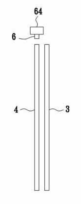
[0054] refer to Figure 3 to Figure 5A preferred embodiment of the liquid crystal display device of the present invention includes a liquid crystal layer 3 , an optical module 4 , a driving circuit 5 and a light emitting diode lamp 6 . The optical module 4 is used to change the distribution of light so that the output light is more evenly distributed than the incident light. The driving circuit 5 is used to provide a constant driving current when the light-emitting diode lamp 6 needs to work normally, and includes a power supply output terminal 51 for outputting the driving current and a feedback for maintaining the constant driving current Control terminal 52 . The light-emitting diode lamp 6 is electrically connected to the driving circuit 5 to receive the...


PUM


Abstract

The invention provides a light emitting diode lamp tube and a liquid crystal display device, wherein the light emitting diode lamp tube comprises a plurality of primary light emitting units which are mutually connected in series; each primary light emitting unit comprises a plurality of secondary light emitting units which are connected in parallel; and each secondary light emitting unit is provided with at least one light emitting diode. The liquid crystal display device provided by the invention comprises the light emitting diode lamp tube, thus the liquid crystal display device of such structure is good for ensuring the uniform brightness of a liquid crystal display screen, the problem that severe nonuniform brightness of the liquid crystal display screen when certain light emitting diode is damaged is overcome, and the liquid crystal display device provided by the invention has the advantages that the driving circuit of the liquid crystal display device can be simplified, and the design cost is lowered.

Description

[0001] technical field [0002] The invention relates to a lamp tube and a display device, in particular to a light emitting diode lamp tube and a liquid crystal display device. Background technique [0003] refer to figure 1 and figure 2 , is a known light-emitting diode lamp tube 1 used in a liquid crystal display device 2 . The liquid crystal display device 2 includes a liquid crystal layer (not shown), an optical module 21 for changing light distribution, and a driving circuit 22 . The driving circuit 22 includes a power supply output 221 and four feedback control terminals 222 . [0004] The light-emitting diode lamp 1 includes a power supply input terminal 11 , four output terminals 12 , four light-emitting units 13 and a printed circuit board (PCB board for short) 14 . Each light-emitting unit 13 includes twenty-two light-emitting diodes 131 connected in series between the power supply input terminal 11 and a corresponding one of the output terminals 12, and each...

Claims


Application Information

Patent Timeline
Patent Type & Authority Applications(China)
IPC IPC(8): F21S2/00F21V23/00G02F1/13357G09G3/36F21Y101/02F21K9/23F21K9/238F21Y115/10
Inventor 余祚尚庄锦清
Owner TPV ELECTRONICS (FUJIAN) CO LTD
Why Eureka
Try Eureka