
Flat tube-fin heat exchanger with double-side vortex generator
A generator and heat exchanger technology, applied in the direction of heat exchanger types, indirect heat exchangers, tubular elements, etc., can solve problems such as increased flow resistance, reduce resistance coefficient, improve heat exchange capacity, and improve heat exchange performance. Effect
- Summary
- Abstract
- Description
- Claims
- Application Information
AI Technical Summary
Problems solved by technology
Method used
Image

Examples
Embodiment Construction
[0016] Below in conjunction with accompanying drawing, the present invention is described in further detail:
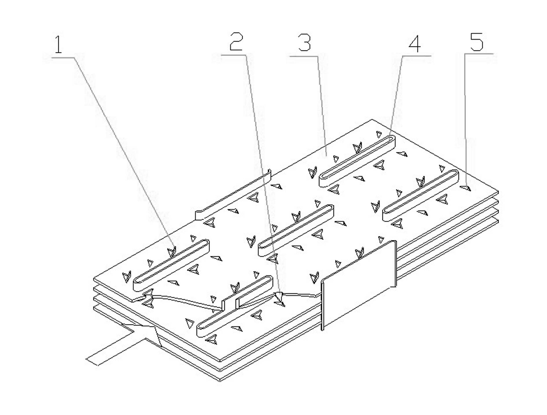
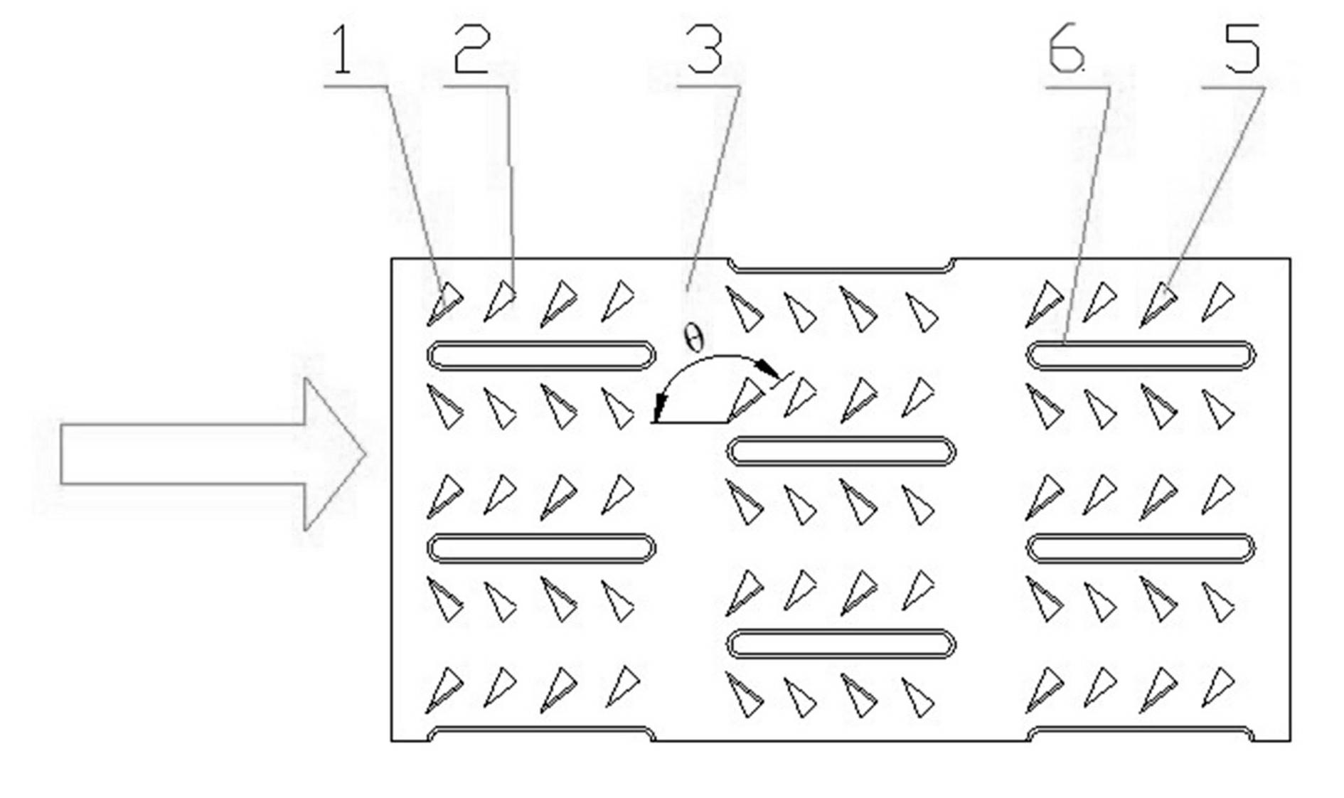
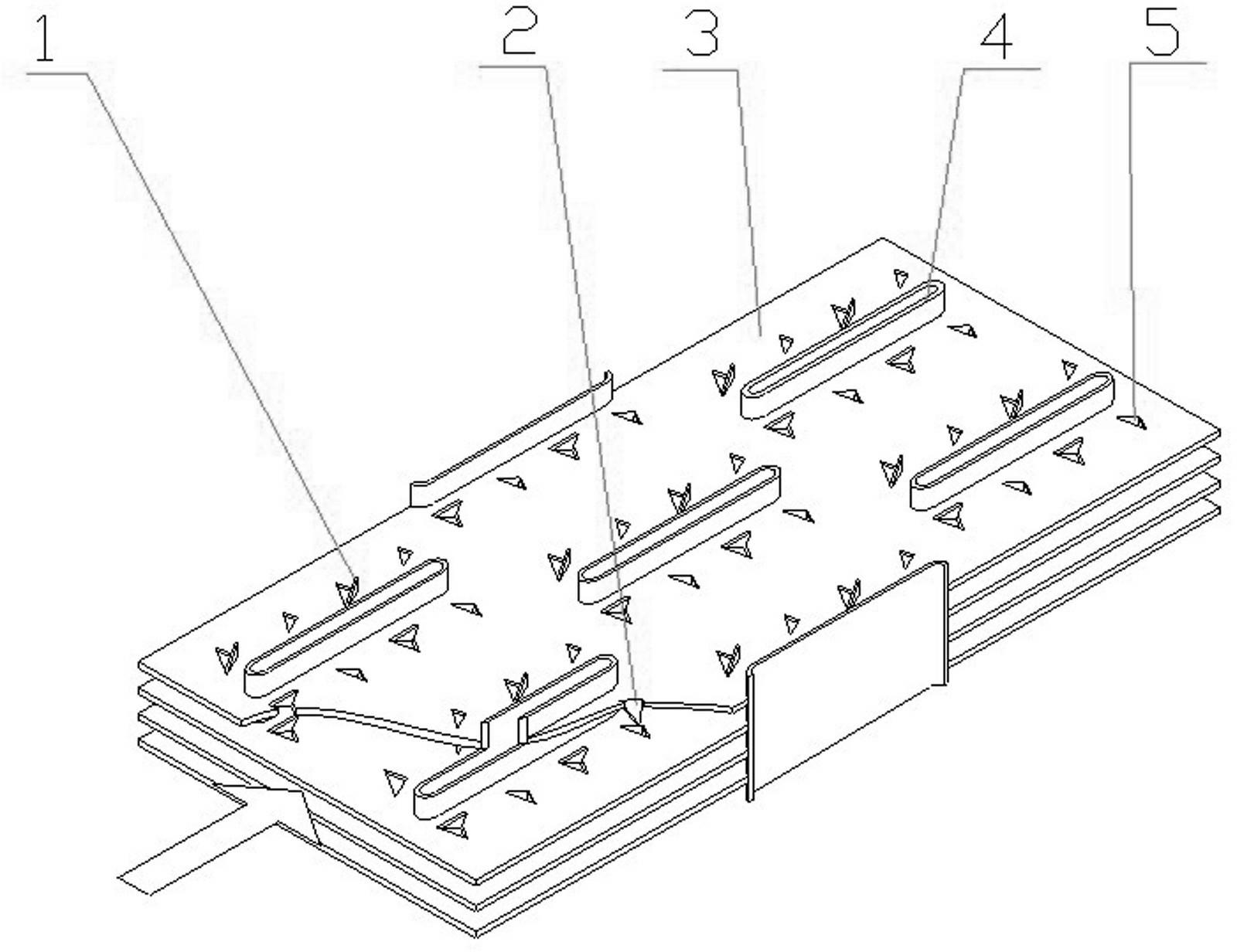
[0017] A double-sided vortex generator type flat tube-fin heat exchanger, including flat tubes 3 arranged in parallel or staggered along the direction of gas flow and fins 4 sleeved on the flat tubes 3, on the fins 4 are arranged Set the holes 6 of the flat tube 3, stamp two pairs of upward triangular vortex generators 1 and two pairs of downward triangular vortex generators 2 on the upper and lower sides of each hole 6, and leave corresponding triangular vortex generators on the fins 4. Small hole 5. The two upward vortex generators 1 and the downward two vortex generators 2 are all perpendicular to the fin 4, the leading edge point of the first pair of upward vortex generators 1 is located at the front tangent of the hole 6, and the second pair of upward vortex generators The leading edge of the vortex generator 1 is positioned at the middle vertical line of th...
PUM
 Abstract
Description
Claims
Application Information