Method and device for mapping demodulation reference signals (DMRS)

A technology for demodulation reference symbols and a mapping method, which is applied in the field of mapping methods and devices for demodulation reference symbols, can solve the problems of inability to estimate interference, inability to achieve pilot orthogonality, and high overhead, thereby reducing mapping complexity and reducing The effect of small receive complexity

Active Publication Date: 2015-04-01
ZTE CORP
View PDF3 Cites 0 Cited by
  • Summary
  • Abstract
  • Description
  • Claims
  • Application Information

AI Technical Summary

Problems solved by technology

[0003] In LTE, common reference symbols (CRS, Common Reference Signal) are used for pilot measurement, that is, all users use common pilots for channel estimation. This kind of CRS requires the transmitting side to additionally notify the receiving end of the transmitted data. What kind of preprocessing method is used, and the overhead is large at the same time. In addition, in multi-user multiple-input multiple-output (MU-MIMO), since multiple UEs are using the same CRS, the orthogonality of the pilots cannot be achieved, so the interference cannot be estimated

Method used


Image

  • Method and device for mapping demodulation reference signals (DMRS)
  • Method and device for mapping demodulation reference signals (DMRS)
  • Method and device for mapping demodulation reference signals (DMRS)

Examples


Embodiment 1

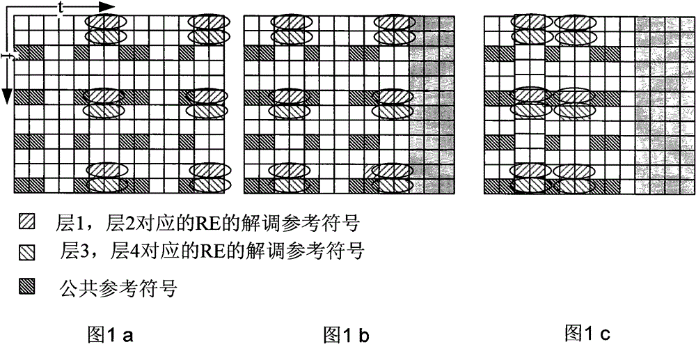
[0069] Referring to Figures 4 to 5, the demodulation reference symbols are subjected to OCC processing, and the OCC-processed demodulation reference symbols are mapped to PRBs according to the positions of the demodulation reference symbols and overhead demodulation reference symbols in each PRB.

[0070] in Figure 4a based on figure 2 The pattern is a designed demodulation reference symbol design pattern based on CDM. According to this pattern, when the number of layers is 3-4, the same demodulation reference symbol pilot overhead is maintained as when the number of layers is 1-2, that is, 24RE / PRB, the frequency domain interval of the demodulation reference symbols corresponding to the same layer is 1 subcarrier; Figure 5a For the case where the demodulation reference symbol overhead is 16RE / PRB, the frequency domain interval of the demodulation reference symbols corresponding to the same layer is 2 subcarriers. Each layer performs CDM multiplexing in the time domain di...

Embodiment 2

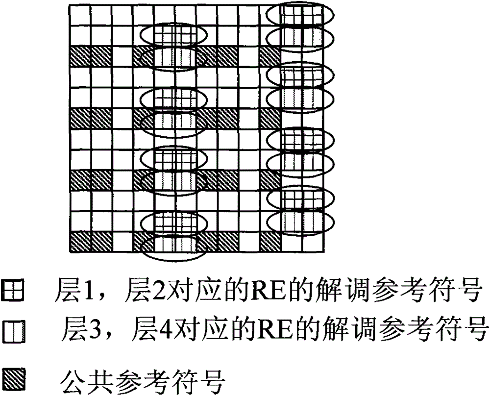
[0088] When the number of layers is 3-4, another specific embodiment of the mapping method based on the present invention is as follows Figure 6 shown. The total overhead remains 24 REs. In the frequency domain direction, the demodulation pilot symbols are equally spaced and divided into 2 groups:

[0089]

[0090]

[0091] And every 2 layers correspond to a group of REs to perform code division multiplexing with an OCC length of 2 on two adjacent OFDM symbols, and when the frequency domain positions of the two groups are cyclically rotated in the frequency domain, the rotation size is the same.

[0092] At the same time, when the number of layers is 3-4, the positions of the total DMRS REs occupied by each layer are the same as the positions of the total DMRS REs occupied by each layer when the number of layers is 1-2, that is, when the number of layers is 1-2 REs are divided into 2 groups, which are assigned to the first 2 layers and the last 2 layers when the number...

Embodiment 3

[0094] When the number of layers is 5-8, the schematic diagram of the mapping method based on the present invention is as follows Figure 7 As shown, in the case of the same overhead and RE position as the layers 3-4 patterns, the length of the OCC is set to 4, and code division multiplexing is performed on 4 OFDM symbols in the time domain. At the same time, all the REs are divided into two groups at equal intervals in the frequency domain, and each group of REs multiplexes 4 layers of DMRS, and frequency division multiplexing is used between the two groups.

[0095] Such as Figure 8 As shown, the demodulation reference symbol mapping device according to the embodiment of the present invention can be applied to the transmitting end of a base station or user equipment (UE), including an OCC processing module and a mapping module;

[0096] The OCC processing module is used to process the demodulation reference symbols with OCC;

[0097] The mapping module is used to map the ...


PUM


Abstract

The invention discloses a method and device for mapping demodulation reference signals (DMRS). The method comprises the following steps: treating the DMRS by orthogonal code cover (OCC) and mapping the DMRS treated by OCC on physical resource blocks (PRB) according to the DMRS overheads and DMRS positions in each PRB, wherein when the extended cyclic prefix (CP) is adopted, the same total DMRS overhead is adopted in each PRB under the condition of different downlink transmission layer numbers. The method and the device have the beneficial effects of ensuring the DMRS to be backward compatible during mapping and reducing the mapping complexity of the transmitting end and the receiving complexity of the receiving end.

Description

technical field [0001] The present invention relates to the communication field, in particular to a mapping method and device for demodulation reference symbols. Background technique [0002] The high-order multi-antenna technology is one of the key technologies of the Long Term Evolution Advanced (LTE-A or LTE-Advanced, Long Term Evolution Advanced) system, and is used to increase the system transmission rate. In order to achieve channel quality measurement and data demodulation after the introduction of high-order multi-antenna technology, the LTE-Advanced system defines two types of pilot symbols: demodulation reference symbols (DMRS, Demodulation ReferenceSignal) and channel quality measurement reference symbols (CSI- RS, Channel State Information-Reference Signal), wherein the DMRS is used for demodulation of a Physical Downlink Shared Channel (PDSCH, PhysicalDownlink Shared Channel). The CSI-RS used for CSI (channel state information) measurement is used for reporting...

Claims


Application Information

Patent Timeline
Patent Type & Authority Patents(China)
IPC IPC(8): H04L5/02H04L27/26
Inventor 孙云锋姜静张文峰张峻
Owner ZTE CORP
Why Eureka
Try Eureka