Tubular member and exhaust system

A technology of exhaust system and tubular body, which is applied in the field of tubular body, can solve the problems that the exhaust system is susceptible to high temperature fluctuations, poor coating durability, and increased component weight, etc., to achieve light weight, small required space, and high durability Effect

Active Publication Date: 2011-07-20
EBERSPACHER EXHAUST TECH GMBH & CO
View PDF5 Cites 5 Cited by
  • Summary
  • Abstract
  • Description
  • Claims
  • Application Information

AI Technical Summary

Problems solved by technology

The disadvantage of such a double-walled design is that on the one hand it requires a relatively large amount of space and on the other hand it increases the weight of the part
If it is attempted to apply an insulating layer on the outside of the tubular body, further problems may arise that the exhaust system is susceptible to high temperature fluctuations so that the coefficient of thermal expansion between the corresponding tubular body and the corresponding coating is even Small deviations also make the durability of these coatings worse

Method used


Image

  • Tubular member and exhaust system
  • Tubular member and exhaust system
  • Tubular member and exhaust system

Examples


Embodiment Construction

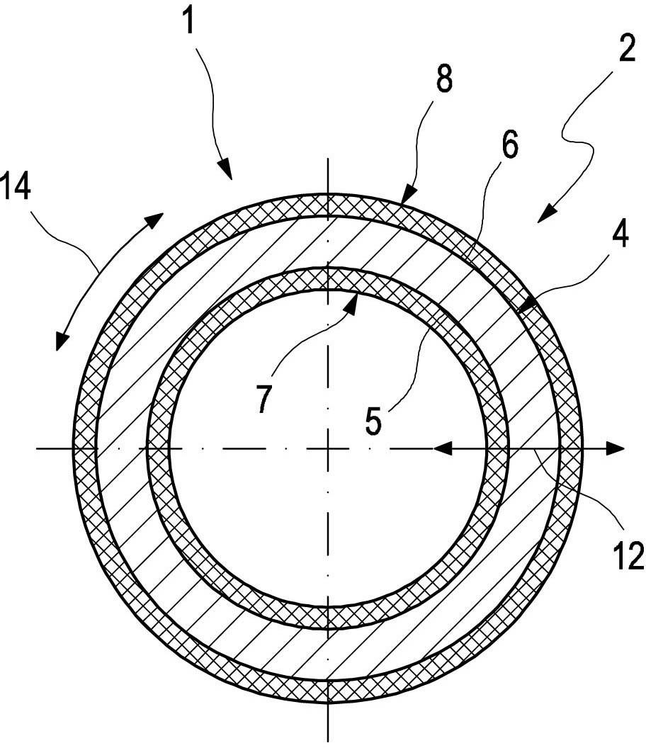
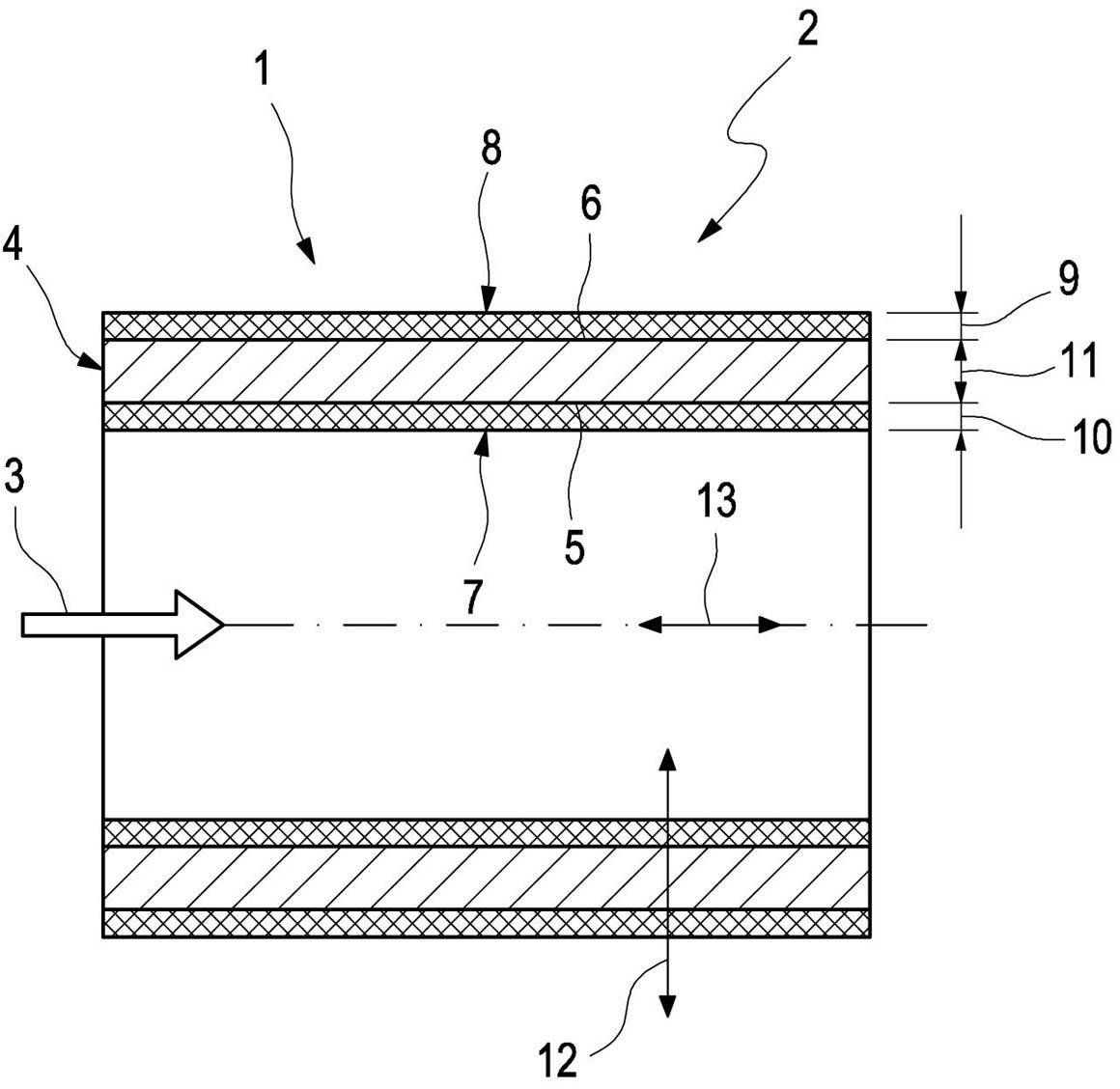
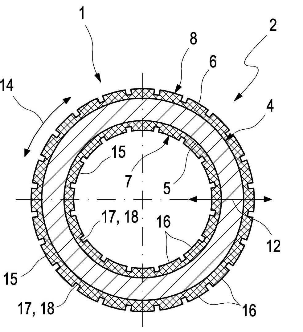
[0026] Figures 1 to 4 in shows the cross-section and longitudinal section of the tubular body 1, respectively. The tubular body 1 preferably forms part of an exhaust system 2 not shown here, so that the exhaust system 2 contains at least one such tubular body 1 . The exhaust system 2 here can obviously also comprise two or more such tubular bodies 1 .

[0027] The exhaust system 2 is suitable for exhausting exhaust gases of an internal combustion engine, which in particular may be arranged in a motor vehicle. The tubular body 1 is therefore also suitable for treating exhaust gases. exist figure 2 and 4 In , the corresponding exhaust gas flow is indicated by an arrow and reference 3.

[0028] exist Figures 1 to 4 In the embodiment, the tubular body 1 is configured as a circular cross-section. Obviously, other cross-sections are also possible in principle. This can be another circular cross-section or any desired geometrical cross-section.

[0029] The tubular body 1...


PUM


Abstract

An exhaust gas-carrying tubular body (1) is provided for an exhaust system (2) of an internal combustion engine, especially of a motor vehicle. The tubular body (1) is provided on its inside (5) facing the exhaust gas and / or on its outside (6) facing away from the exhaust gas with a coating (7, 8), which is formed of a composite ceramic based on nanoparticles.

Description

technical field [0001] The invention relates to a tubular body for the treatment of exhaust gas for the exhaust system of an internal combustion engine, in particular of a motor vehicle. The invention also relates to an exhaust system having at least one such tubular body. technical background [0002] In an exhaust system, it is necessary to achieve external or internal thermal insulation for various reasons. One of these is the need to protect the exhaust system from the high temperatures of the exhaust gases conveyed in the exhaust system. To this end, the exhaust system can be thermally insulated from the outside, at least in certain regions. On the other hand, it is necessary to maintain the exhaust gas conveyed in the exhaust system at a high temperature level, for example in order to be able to reach the predetermined operating temperature or regeneration temperature suitable for certain exhaust gas treatment devices as soon as possible, or in order to be able to ma...

Claims


Application Information

Patent Timeline
Patent Type & Authority Applications(China)
IPC IPC(8): F01N13/14F01N13/16
CPCF01N2530/26F01N3/28F01N2240/02F01N13/08F28F13/185F28F13/18F28F21/04F16L59/143F01N13/14F01N2510/02F28F2255/20Y02A50/20
Inventor 约尔格·瓦斯特勒罗尔夫·耶巴辛斯基乔治·维尔特马蒂亚斯·格林
Owner EBERSPACHER EXHAUST TECH GMBH & CO
Why Eureka
Try Eureka