Wig vehicle excluding horizontal stabilizer

A ground-effect wing ship and horizontal stabilizer technology, which is applied in the direction of ship hull, ship construction, seaplane, etc., can solve the problems of instability, difficulty in designing a horizontal stabilizer, and no development, and achieves a reduction in the weight of the hull and improves the convenience of production. Effect

Inactive Publication Date: 2011-07-20
WING SHIP TECH CO LTD
View PDF7 Cites 3 Cited by
  • Summary
  • Abstract
  • Description
  • Claims
  • Application Information

AI Technical Summary

Problems solved by technology

[0004] That is, it is difficult to design an appropriate horizontal tail, and, depending on the situation, unexpected instability may occur during navigation
[0005] however, no alternative to the vertical stabilizer has been developed so far

Method used


Image

  • Wig vehicle excluding horizontal stabilizer
  • Wig vehicle excluding horizontal stabilizer
  • Wig vehicle excluding horizontal stabilizer

Examples


Embodiment Construction

[0032] Hereinafter, the wing structure of the ground-effect wing ship of the present invention will be described in detail with reference to the accompanying drawings.

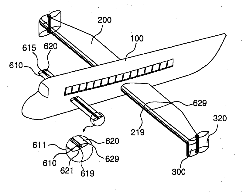
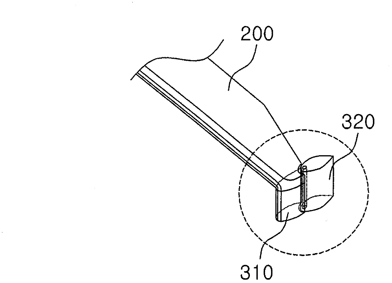
[0033] figure 2 It is the first embodiment of the wing structure of the ground-effect wing ship of the present invention; image 3 for figure 2 Main wing and downward wing profile in ; Figure 4 It is a schematic diagram of having ribs and spars inside the main wing; Figure 5 It is a schematic diagram of the joint part of the downward wing; Image 6 It is a schematic diagram of an embodiment of the shape of the lower part of the downward wing; Figure 7 It is a schematic diagram of the downward wing structure of another embodiment; Figure 8 and Figure 9 for as Figure 7 A schematic diagram of an embodiment of the shape of the lower part of the downward wing in the structure shown.

[0034] Next, in the wing structure of the ground effect ship described in the drawings, it has a left / right side sym...


PUM


Abstract

The present invention relates to a WIG vehicle wing structure characterized in that in the WIG vehicle comprising a body including a fuselage, a wing unit including a main wing, and a propulsion unit including an engine, the wing unit comprises a main wing protruding out from the lateral center of the WIG vehicle fuselage, a downward wing which is vertically and downwardly installed on the outer tip of the main wing, and a canard which protrudes out horizontally from the front end of the fuselage, which is in the moving direction of the WIG vehicle from the main wing. The downward wing comprises a downward plate which is integrally and downwardly installed on the tip of the main wing, and a variable rudder which is installed to face the rear surface of the downward plate. In the lateral cross section shape, the front surface portion including the leading edge is round at a proper thickness to prevent flow separation, the thickness of a portion having the peak thickest narrows, and the trailing edge is sharp and straight. The vertical cross section of the entire downward wing is airfoil-shaped. Accordingly, the present invention is able to resolve the design problem of the horizontal stabilizer caused by a ground effect because the WIG vehicle comprises a canard for stabilizing vertical disturbance instead of a horizontal stabilizer.

Description

technical field [0001] The invention relates to a wing structure of a ground-effect wing ship, in particular to a ground-effect wing ship hull and a wing shape for forming a canard instead of a horizontal tail to form the wing structure of a ground-effect wing ship. Background technique [0002] Generally, in an aircraft and a ground effect ship, a horizontal stabilizer is used in order to suppress the vertical roll. Considering the downwash angle caused by the front main wing, the horizontal stabilizer has an appropriate size and initial angle. [0003] However, on a ground effect boat, the change in the downwash angle depends not only on artificial shapes such as the flap change of the main wing, but also on the sailing altitude. That is, at a low height, the flow tends to become parallel due to the action of the water surface, so that the size of the downwash angle becomes smaller, and at a high height, the size returns to the original value. [0004] That is, it is dif...

Claims


Application Information

Patent Timeline
Patent Type & Authority Applications(China)
IPC IPC(8): B63B1/16
CPCB64C23/065B64C35/003Y02T50/164B64C39/12B64C5/08B64C23/076Y02T50/10B63B1/16B63B1/18
Inventor 姜昌求李韩镇李昌珉
Owner WING SHIP TECH CO LTD
Why Eureka
Try Eureka