Drill bit with weight and torque sensors

A technology of torque sensor and load sensor, applied in the system field of drill bit, can solve problems such as inaccurate estimation

Inactive Publication Date: 2011-07-20
BAKER HUGHES INC
View PDF4 Cites 6 Cited by
  • Summary
  • Abstract
  • Description
  • Claims
  • Application Information

AI Technical Summary

Problems solved by technology

[0003] Illustratively, bit torque and weight-on-bit (also referred to herein as "pressure" or "load") are estimated using measurements made by sensors disposed on the BHA (i.e., away from the bit), which estimates may be not accurate

Method used


Image

  • Drill bit with weight and torque sensors
  • Drill bit with weight and torque sensors
  • Drill bit with weight and torque sensors

Examples


Embodiment Construction

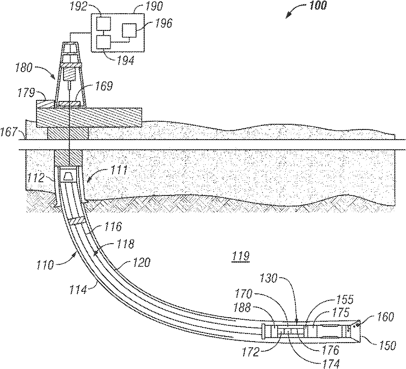
[0013] figure 1 is a schematic diagram of an exemplary drilling system 100 that may utilize the drill bits disclosed herein for drilling a wellbore. figure 1 A wellbore 110 is shown comprising an upper portion 111 in which a casing 112 is installed and a lower portion 114 being drilled by means of a drill string 118 . The drill string 118 includes a tubular member 116 that carries a drilling assembly 130 (also referred to as a bottom hole assembly or "BHA") at its bottom end. The tubular element 116 may be made up by joining sections of drill pipe or it may be coiled tubing. A drill bit 150 is attached to the bottom end of the BHA 130 for fracturing the formation to drill a selected diameter wellbore 142 in the formation 119 . The terms "wellbore" and "borehole" are used synonymously herein.

[0014] Drill string 118 is shown conveyed into wellbore 110 from drill rig 180 at surface 167 . For illustrative purposes, figure 1 The exemplary rig 180 shown in is an onshore rig....


PUM


Abstract

A drill bit made according to one embodiment includes at least one of a weight sensor and a torque sensor configured to provide signals representative of the weight and torque on the drill bit when the drill bit is used for cutting into a formation. A circuit may be configured to process signals from the weight and torque sensors to provide estimate values of the weight and torque on the bit when the drill bit used for cutting into the formation.

Description

technical field [0001] The present invention generally relates to drill bits and systems using such drill bits, wherein the drill bits include sensors for providing measurements related to parameters of interest. Background technique [0002] An oil well (wellbore) is typically drilled with a drill string comprising a tubular element having a drilling assembly (also known as a bottom hole assembly or "BHA") with a drill. The drill bit is rotated to fracture the formation so that the wellbore is drilled. The BHA includes equipment and sensors for providing information on various parameters related to the drilling operation (Drilling Parameters), the condition of the BHA (BHA Parameters), and the formation surrounding the wellbore being drilled (Formation Parameters). Drilling parameters include the weight-on-bit ("WOB"), the rotational speed of the drill bit and BHA (revolutions per minute or "RPM"), the rate of penetration of the bit into the formation ("ROP") and the flow...

Claims


Application Information

Patent Timeline
Patent Type & Authority Applications(China)
IPC IPC(8): E21B44/00E21B47/00G01L1/22
CPCE21B47/01E21B12/00E21B12/02
Inventor T·T·郑E·C·沙利文D·普理查德
Owner BAKER HUGHES INC
Why Eureka
Try Eureka