Electric motor

A technology of electric motors and brushes, which is applied in the field of electric motors, and can solve the problems of increasing the size of the armature shaft direction and reducing the space factor of the windings, etc.

Active Publication Date: 2011-07-20
MITSUBA CORP
View PDF13 Cites 12 Cited by
  • Summary
  • Abstract
  • Description
  • Claims
  • Application Information

AI Technical Summary

Problems solved by technology

Therefore, in the case where the coil windings 93A and 93C are wound in an overlapping manner outside the already wound coil windings 93A and 93C in the armatur...

Method used


Image

  • Electric motor
  • Electric motor
  • Electric motor

Examples


Embodiment Construction

[0077] Hereinafter, an embodiment of the present invention will be described. In addition, in the drawings corresponding to the following description, a part of the reference numerals indicating the common structure in the plurality of embodiments may be omitted.

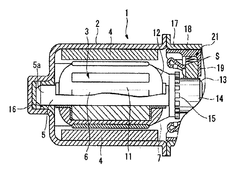
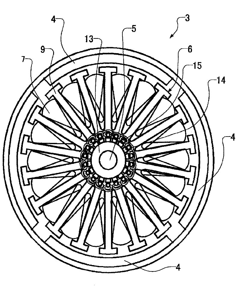
[0078] Then, based on Figure 1 to Figure 5 The motor 1 according to the first embodiment of the present invention described is used as a drive device for a wiper motor, a window motor, a fan motor, etc. of an automobile, for example, and has: a bottomed cylindrical yoke 2; The magnet 4 is fixed on the inner wall of the yoke 2; and the armature 3 is surrounded by the magnet 4 and arranged in the yoke 2, and is supported so as to be rotatable relative to the yoke 2. The magnet 4 is magnetized to 4 poles, and the motor 1 is a 4 pole type motor, and the number of pole pairs is two.

[0079] The armature 3 is configured to include: an armature iron core 6 fixed on the rotating shaft 5; an armature coil 7 wound on the armat...


PUM


Abstract

The present invention relates to an electric motor, wherein magnets (4) have two pairs of poles, the number of teeth (9) is 18, and the commutator has 18 segments (14). Winding wires (12, 25) for forming armature coils (7) are formed by first conductive wires (110) or second conductive wires (120). The winding wire (25) has first coil winding wires (7A) and second coil winding wires (7B). The coil winding wires are each wound around four teeth (9) adjacent to each other. An end section (31) of a second coil winding wire is connected to a segment (14) adjacent to a segment mounted at a position which is point symmetric about a segment to which an end section (30) of a first coil winding wire is connected. The rotational speed of an armature can be changed by switching the conduction of electricity among three brushes. This configuration reduces vibration and operating noise of the electric motor and facilitates mounting of connecting wires and the winding wires.

Description

Technical field [0001] The present invention relates to an electric motor mounted in an automobile or the like, and particularly relates to an electric motor capable of changing the rotation speed of an armature included in the electric motor. This application is based on Japanese Patent Application No. 2008-170738, Japanese Patent Application No. 2008-170739 and Japanese Patent Application No. 2008-170740 filed in Japan on June 30, 2008, and Japanese Patent Application No. 2009-039598 filed in Japan on February 23, 2009 , And Special Application No. 2009-068640 filed in Japan on March 19, 2009, claiming priority, and its content is quoted here. Background technique [0002] Generally, as a motor mounted in a car, a commutator motor with a brush is often used. This motor has: a cylindrical yoke; a plurality of permanent magnets arranged on the inner peripheral surface of the yoke; and an armature arranged inside the permanent magnets so as to be rotatable with respect to the yok...

Claims


Application Information

Patent Timeline
IPC IPC(8): H02K23/26H02K23/04H02K23/20
CPCH02K23/20H02K23/30Y02T10/641Y02T10/64
Inventor 坂田宪儿川岛义亲
Owner MITSUBA CORP
Why Eureka
Try Eureka