Drift folded marsh gas collector

A biogas collector and biogas technology, applied in the field of biogas collection equipment, can solve the problems of long recovery time, burns, and poor air circulation, and achieve the effects of quick cost recovery, small investment, and reduction of danger and work difficulty.

Inactive Publication Date: 2011-07-27
宋志祥
View PDF5 Cites 10 Cited by
  • Summary
  • Abstract
  • Description
  • Claims
  • Application Information

AI Technical Summary

Problems solved by technology

Because the dredging port is reserved for sealing, it is often designed very small. Once people enter the main pool completely, they will actually enter a space with no air circulation. In addition, the manure contains a large amount of methane and carbon dioxide, which leads to the operation below. People were poisoned to death, burned and other accidents in the pool
[0004] Secondly, taking a new pond with a volume of 20 cubic meters as an example, according to the traditional needs, it costs about 6,000 yuan. The cost has already made it difficult for many farmers to accept, and it costs about 5,000 yuan without state subsidies.
Produce 360 ​​cubic meters of biogas per year. Calculated at 2.6 yuan per cubic meter at the current price of natural gas, you can only recover 936 yuan a year. It takes more than 5.3 years to recover the investment, and the recovery time is relatively long
[0005] In addition, the existing devices are prone to "storm pools", that is, the biogas pools continue to produce biogas, and after the pressure in the airtight gas chamber is high, the storm pool is not used in time, resulting in damage to the pool body. At the same time, the current biogas collection equipment does not store Considering gas, most of them adopt the method of collecting on demand, which is very inconvenient to use

Method used


Image

  • Drift folded marsh gas collector
  • Drift folded marsh gas collector
  • Drift folded marsh gas collector

Examples


Embodiment Construction

[0015] The present invention will be further described below in conjunction with the accompanying drawings.

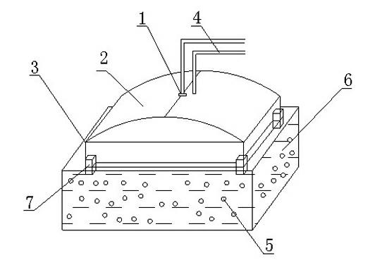
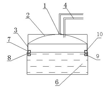
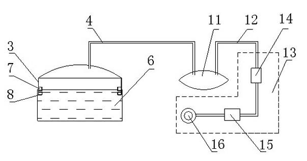
[0016] Such as figure 1 , figure 2 , a drifting folding biogas collector, which consists of a biogas probe 1, a suspension cover 2, a suspension cover support 3, a gas delivery pipe 4, and a floating device 7. The suspension cover support 3 floats in the fermentation tank 6, and the suspension cover 2 is installed on the suspension cover support. 3 to form an air chamber, and the bottom of the suspension cover support 3 is equipped with an array of floating devices 7. The floating device 7 is immersed in the fermentation liquid of the fermentation tank 6. The biogas probe 1 is located above the suspension cover 2 and is in contact with the suspension cover 2 when it is inflated. The air pipe 4 passes through the suspension cover 2 and communicates with the air chamber, the biogas probe 1 is connected to the compressor through the control circuit, and the load end of ...


PUM


Abstract

The invention discloses a drift folded marsh gas collector. The drift folded marsh gas collector comprises a marsh gas probe (1), a suspension cover (2), a suspension cover bracket (3), a gas pipe (4) and floating devices (7), wherein the suspension cover bracket (3) floats in a fermenting tank (6); the suspension cover (2) is arranged on the suspension cover bracket (3) to form a gas chamber; a plurality of groups of floating devices (7) are arranged at the bottom of the suspension cover bracket (3), and the floating devices (7) are immersed into fermentation liquor of the fermenting tank (6); the gas pipe (4) passes through the suspension cover (2) and is communicated with the gas chamber; the marsh gas probe (1) is connected with a compressor through a control circuit; and the load end of the compressor is connected with the gas pipe (4). The drift folded marsh gas collector has the advantages that: the collector is flexibly manufactured according to the size of the fermenting tank, has low investment and quick cost recovery, simultaneously can store marsh gas, and is safety and reliable; and because the structure is folded, the collector is not affected by the shape of the tank, is very suitable for free collection at various indoor and outdoor marsh gas production places, and reduces the danger and the working difficulty of an aeration tank.

Description

technical field [0001] The invention relates to biogas collection equipment, in particular to a drifting and folding biogas collector. Background technique [0002] With the development of my country's biogas science and technology and the promotion of rural household biogas, biogas equipment has been widely used. Most of the existing biogas equipment adopts the sealed structure of the biogas digester. The biogas digester is actually a fermentation and submerged gas storage device. Fermentation is automatic, and the traditional thinking is based on the overall design, which will bring many negative effects to the utilization of biogas. [0003] First of all, digging out pond silt is an important reason why many traditional biogas buildings are built instead of being used. At the same time, the risk factor of sealed biogas digesters is relatively high, while fixed biogas digesters have to be dredged once a year according to production needs. The environment in the pond is very...

Claims


Application Information

Patent Timeline
Patent Type & Authority Applications(China)
IPC IPC(8): C02F11/04C12M1/107
CPCY02E50/343C12M23/26C12M23/56C12M23/36C12M21/04Y02E50/30
Inventor 宋志祥
Owner 宋志祥
Why Eureka
Try Eureka