Pneumatically-controlled locking device for mine air door

A pneumatic control and locking device technology, which is applied in mine/tunnel ventilation, mining equipment, door/window accessories, etc., can solve the problems of large ventilation resistance, simultaneous opening of dampers, air leakage, etc., and achieve the effect of flexible opening

Inactive Publication Date: 2011-07-27
焦作煤业(集团)新乡能源有限公司
View PDF6 Cites 12 Cited by
  • Summary
  • Abstract
  • Description
  • Claims
  • Application Information

AI Technical Summary

Problems solved by technology

However, there is a problem in this structure that automatic interlocking cannot be realized between the two dampers, and it is easy to cause the two dampers to open simultaneously, resulting in air leakage and destroying the normal operation of the ventilation system. At the same time, due to the large ventilation resistance, the negative pressure difference of the dampers is large Difficulty opening the damper

Method used


Image

  • Pneumatically-controlled locking device for mine air door
  • Pneumatically-controlled locking device for mine air door
  • Pneumatically-controlled locking device for mine air door

Examples


Embodiment Construction

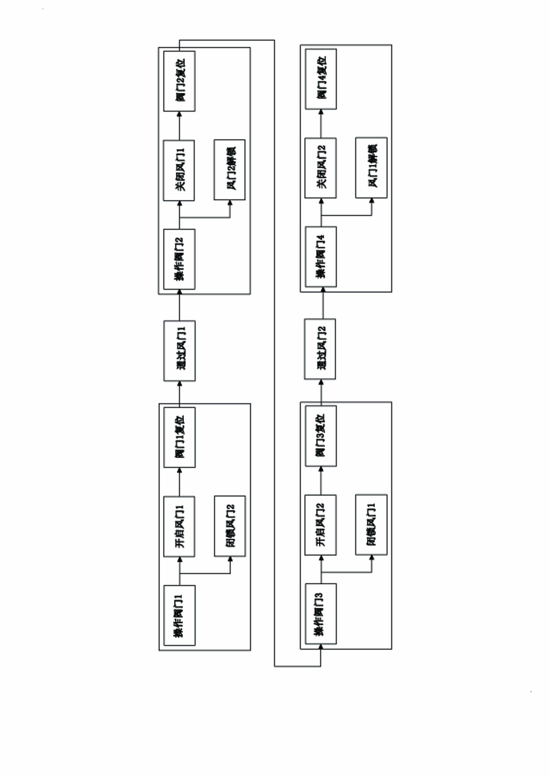
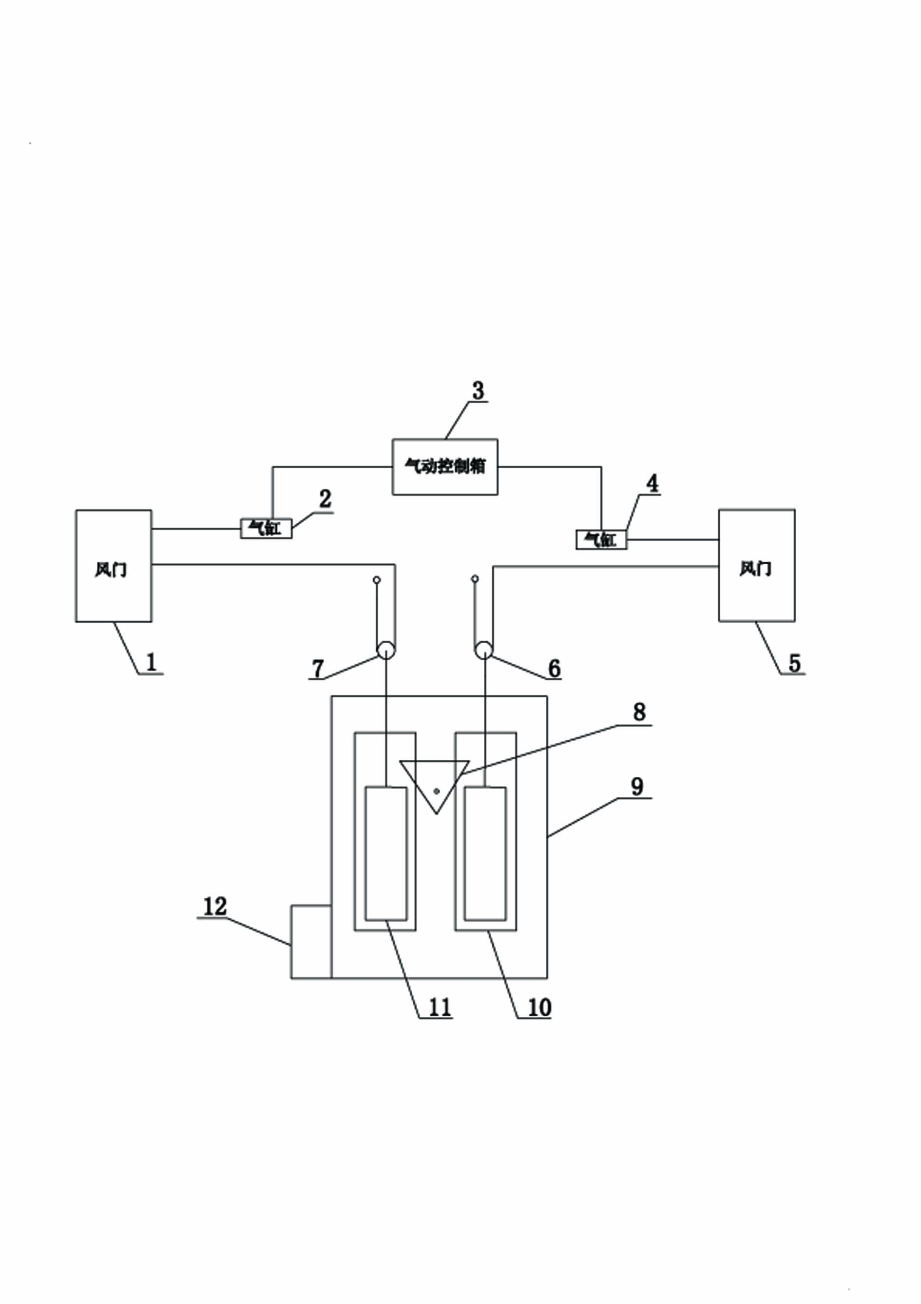
[0014] Such as figure 1 , figure 2 As shown, the present invention comprises a first damper 1, a second damper 5, a first cylinder 2 and a second cylinder 4, a pneumatic control box 3, a mechanical interlock box 9, a muffler 12, a first movable pulley 7 and a second movable pulley 6, The pneumatic control box 3 is connected to the first air cylinder 2 and the second air cylinder 4 through valves respectively, the first air cylinder 2 is connected to the first damper 1, the second air cylinder 4 is connected to the second damper 5, and the two sliding bodies 11 in the mechanical interlocking box 9 Connect to the first damper 1 and the second damper 5 through the first movable pulley 7 and the second movable pulley 6 respectively. For eliminating exhaust noise, a muffler 12 is installed at the exhaust port of the mechanical interlock box 9 .

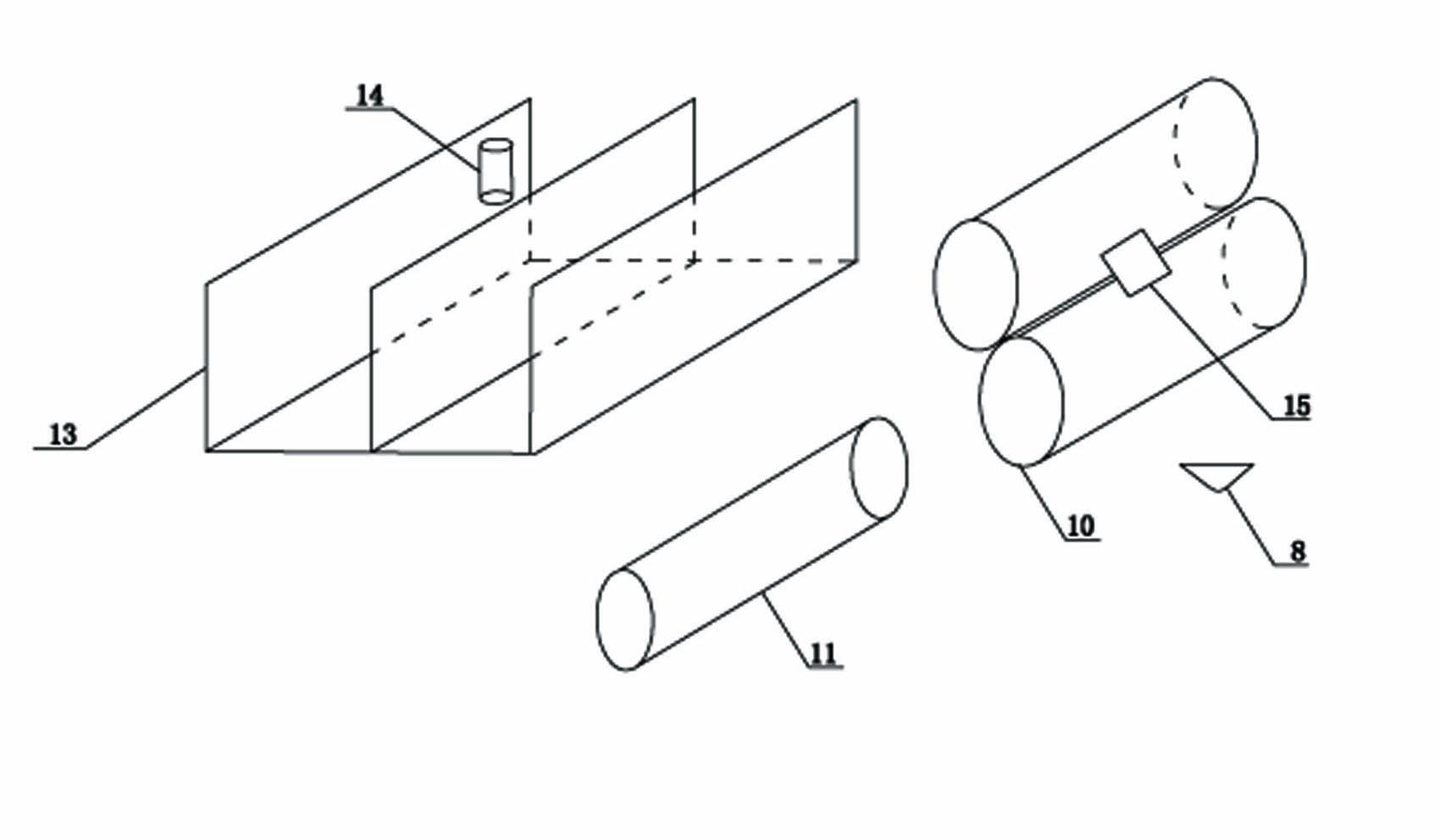
[0015] Such as image 3 As shown, the mechanical interlock box 9 includes a fixed plate 13, a sliding body 11, a sleeve 10 and a locki...


PUM


Abstract

The invention discloses a pneumatically-controlled locking device for a mine air door, comprising a first air door, a second air door, a first gas cylinder and a second gas cylinder, and also comprises a pneumatic control box, a mechanical interlock box, a muffle, a first traveling block and a second traveling block, wherein the pneumatic control box is connected with the first gas cylinder and the second gas cylinder respectively by valves; the first gas cylinder is connected with the first air door; the second gas cylinder is connected with the second air door; the mechanical interlock box is connected with the first air door and the second air door respectively by the first traveling block and the second traveling block; and the muffle is fixed on the mechanical interlock box. The pneumatically-controlled locking device for the mine air door can ensure a ventilation system to work normally, utilizes the gas cylinders to pull guide pulleys, simultaneously utilizes a mechanical interlock so as to enable the two air doors not to be opened simultaneously, and has the automatic interlocking function.

Description

technical field [0001] The invention relates to a damper control device of an underground ventilation system in a coal mine, in particular to a pneumatically controlled locking device for a mine damper. Background technique [0002] In coal mines, pedestrians and vehicles will affect the ventilation system of the roadway. If the two dampers in the roadway are opened at the same time, it will cause a short circuit of the incoming air flow, and make some areas and working faces in a breeze or no wind state, resulting in excessive gas accumulation. , a threat to the safety of workers. At present, most of the dampers in the underground ventilation system of coal mines in my country are in the form of single or double doors. Many mechanized mine dampers are controlled by electro-hydraulic locking, which has defects such as high cost and difficult maintenance. In order to effectively solve the problem of reversing the direction of the wind under the two conditions of positive and...

Claims


Application Information

Patent Timeline
Patent Type & Authority Applications(China)
IPC IPC(8): E21F1/10E05F15/02E05C7/00E05F15/50
Inventor 魏世义陈新明李长军王长富张金富马国流陈舰艇
Owner 焦作煤业(集团)新乡能源有限公司
Why Eureka
Try Eureka