Method for improving angular displacement measurement accuracy of optical fiber gyroscope

A technology of fiber optic gyroscope and measurement accuracy, which is applied in the direction of speed measurement, angle measurement, and Sagnac effect gyroscope, etc., which can solve the problems of inaccurate results and non-linear relationship of fiber optic gyroscope, and achieve Effect of Accuracy Improvement

Inactive Publication Date: 2011-07-27
ZHEJIANG UNIV
View PDF6 Cites 19 Cited by
  • Summary
  • Abstract
  • Description
  • Claims
  • Application Information

AI Technical Summary

Problems solved by technology

[0015] This method can achieve relatively high accuracy, but it does not take into account the nonlinear relationship between the scale factor of the

Method used


Image

  • Method for improving angular displacement measurement accuracy of optical fiber gyroscope
  • Method for improving angular displacement measurement accuracy of optical fiber gyroscope
  • Method for improving angular displacement measurement accuracy of optical fiber gyroscope

Examples


Embodiment Construction

[0038] The fiber optic gyroscope is a sensor that measures angular velocity, and its output expression is:

[0039] F=KΩ+D 0 (5)

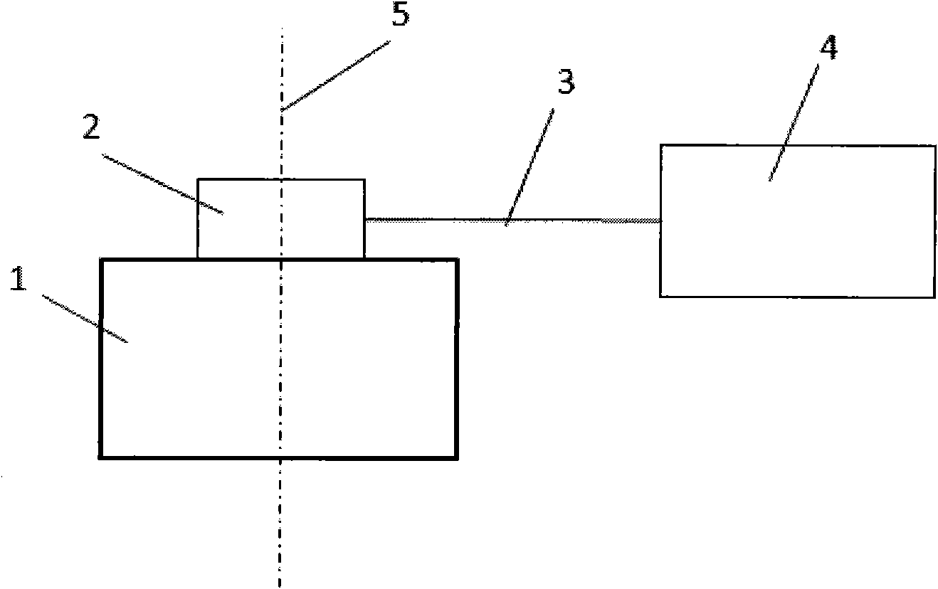
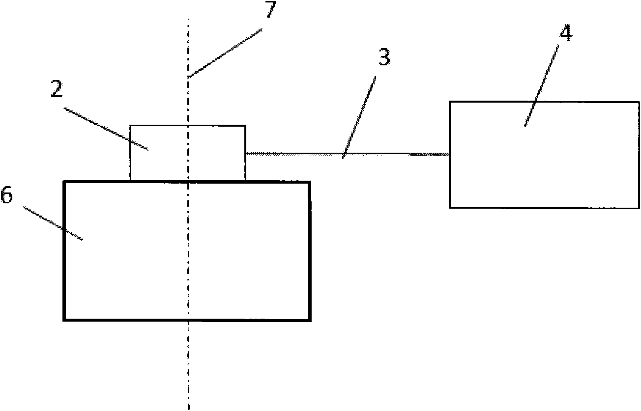
[0040] In formula (5), F is the output of the fiber optic gyroscope, K is the scaling factor of the fiber optic gyroscope, Ω is the input angular velocity, and D 0 is the zero bias of the fiber optic gyroscope. K and D 0 is the quantity calibrated in advance, the input angular velocity Ω can be calculated according to the output F of the fiber optic gyroscope. When the fiber optic gyroscope and the rotating device under test are fixed and the input axis is parallel to the rotating shaft under test, the measured angular velocity is the angular velocity of the rotating device under test. By integrating it, the angular velocity of the rotating device under test can be obtained. displacement.

[0041] Below in conjunction with accompanying drawing, the present invention will be further described (with reference to ima...


PUM


Abstract

The invention discloses a method for improving angular displacement measurement accuracy of an optical fiber gyroscope. The method comprises the following steps of: (1) fixing the optical fiber gyroscope on a high-accuracy rotary table to keep a measuring shaft of the optical fiber gyroscope in parallel to a rotating shaft of the high-accuracy rotary table; (2) marking scale factors of the optical fiber gyroscope at different rotary table input angular rates to acquire a correspondence table between the angular rates and the scale factors; (3) taking the optical fiber gyroscope off the high-accuracy rotary table and fixing on a measured rotating device to keep the measuring shaft of the optical fiber gyroscope in parallel to the rotating shaft of the measured rotating device; (4) solving an average value of output values of the optical fiber gyroscope in a testing time under the condition that the measured rotating device is static; (5) rotating the measured rotating device and continuously recording each output value of the optical fiber gyroscope; and (6) calculating a rotation angle, namely the angular displacement of the rotating device by using the correspondence table in thestep (2), the output average value in the step 4 and each output value in the step (5).

Description

technical field [0001] The invention designs a measurement technology, and in particular relates to a technology for improving the measurement accuracy of an optical fiber gyroscope for measuring angular displacement. Background technique [0002] The fiber optic gyroscope is a sensor for measuring angular velocity. If the fiber optic gyroscope is installed on the rotating device, and the angular velocity of the rotating device is measured and integrated, the angular displacement of the rotating device due to the rotation can be obtained. Because the fiber optic gyroscope has the characteristics of small size and short start-up time, it is especially suitable for the application of angular displacement measurement. [0003] The fiber optic gyroscope is a sensor that measures angular velocity, and its output expression is: [0004] F=KΩ+D 0 (5) [0005] In the formula, F is the output of the fiber optic gyroscope, K is the scaling factor of the fiber optic ...

Claims


Application Information

Patent Timeline
IPC IPC(8): G01C1/00G01P9/00G01C19/64
Inventor 金杭周一览李赓黄腾超舒晓武刘承
Owner ZHEJIANG UNIV
Why Eureka
Try Eureka