Faraday electromagnetic induction tester

A technology of electromagnetic induction and magnetic induction intensity, which is applied in the direction of instruments, educational tools, teaching models, etc., can solve the problems of inability to study the induced electromotive force quantitatively, and achieve the effect of simple structure

Active Publication Date: 2011-07-27
SHANDONG YUANDA LLONGWILL EDUCATIONAL SCI & TECH LTD
View PDF2 Cites 4 Cited by
  • Summary
  • Abstract
  • Description
  • Claims
  • Application Information

AI Technical Summary

Problems solved by technology

[0003] In order to overcome the problem that the existing Faraday electromagnetic induction experimenter cannot quantitatively study the relationship between the induced electromotive force E and the rate of change of magnetic induction intensity ΔΦ / Δt, the present invention provides a method that can qualitatively and quantitatively study the relationship between the induced electromotive force E and the rate of change of magnetic flux ΔΦ / Δt Faraday Electromagnetic Induction Experimental Apparatus for the Relationship of Δt

Method used


Image

  • Faraday electromagnetic induction tester
  • Faraday electromagnetic induction tester
  • Faraday electromagnetic induction tester

Examples


Embodiment Construction

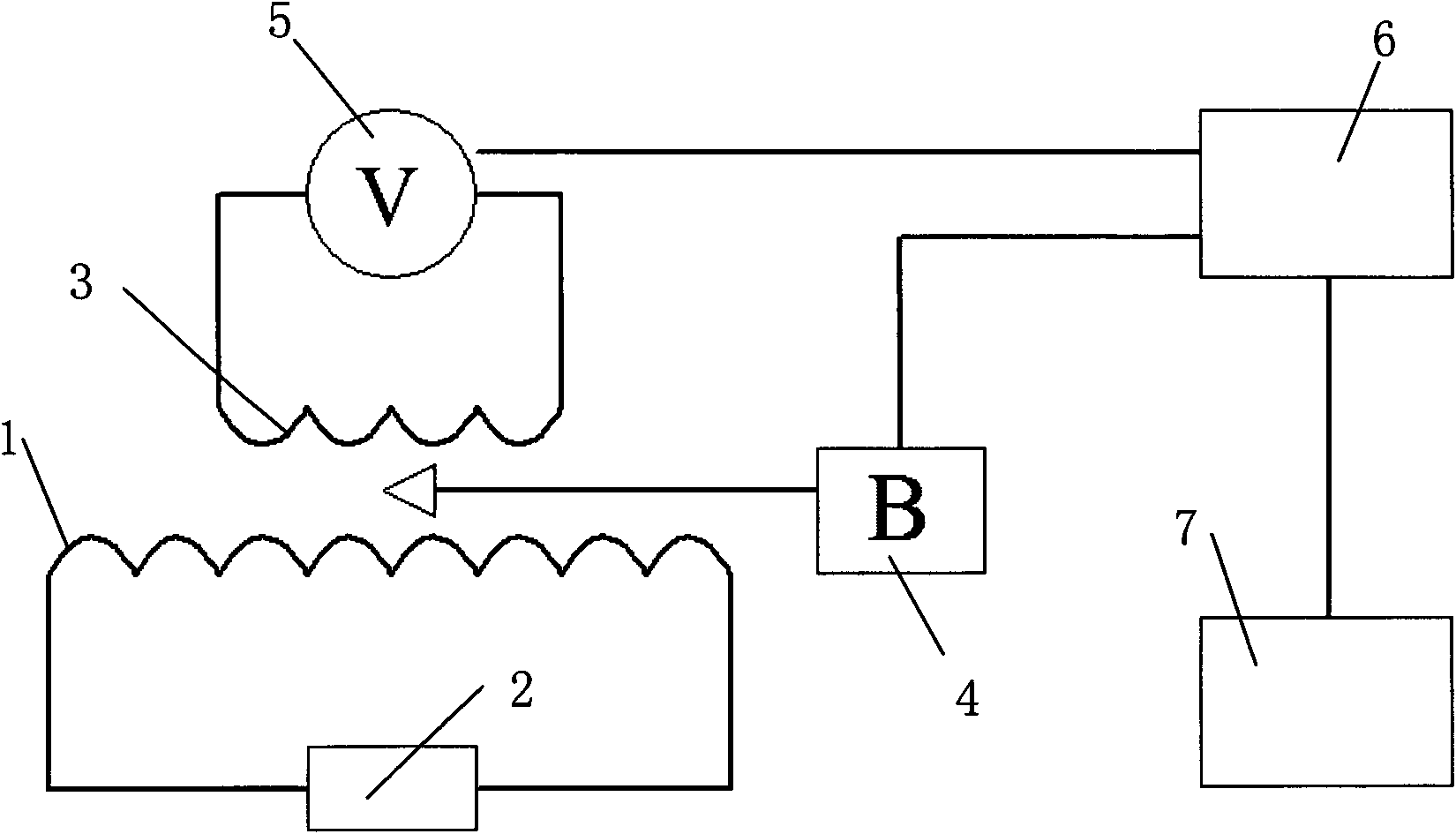
[0038] Such as figure 1 As shown, the Faraday electromagnetic induction experimenter of the present invention includes a solenoid 1 , a voltage linearly varying power supply 2 , an induction coil 3 , a magnetic induction sensor 4 , a voltage sensor 5 , a data collector 6 and a computer 7 . The solenoid 1 is connected to the voltage linearly changing power supply 2, the induction coil 3 is coaxially sleeved outside the solenoid 1, and a magnetic induction sensor 4 is placed inside the induction coil 3 to measure the magnetic induction at the induction coil 3. A voltage sensor 5 is connected to the induction coil 3 for measuring the induced electromotive force. Both the magnetic induction sensor 4 and the voltage sensor 5 are connected to the computer 7 through the data collector 6, and the computer 7 displays the data graph of the magnetic induction and the voltage changing with time.

[0039] The solenoid (primary coil) 1 is connected to the voltage output terminal of the vol...


PUM


Abstract

The invention provides a faraday electromagnetic induction tester, which comprises a solenoid, an induction coil, a magnetic flux density sensor, a voltage sensor, a voltage linear change power supply, a data collector, and a computer. The solenoid is connected with the voltage linear change power supply; the induction coil is arranged outside the solenoid; the magnetic flux density sensor used for measuring the magnetic flux density at the position of the induction coil is arranged in the induction coil; the induction coil is connected with the voltage sensor used for measuring an induced electromotive force; both the magnetic flux density sensor and the voltage sensor are connected with the computer through the data collector; the data collector reads the data collected by the magnetic flux density sensor and the voltage sensor, and transmits the data to the computer. The faraday electromagnetic induction tester has simple structure, can quantitatively research the relationship between the induced electromotive force E and the magnetic flux density change rate Delta B/Delta t and the relationship between the induced electromotive force E and the coil turns n, thus verifying the faraday law of electromagnetic induction.

Description

technical field [0001] The invention relates to an experimental device for Faraday electromagnetic induction experiments, in particular to a Faraday electromagnetic induction experimental device capable of quantitatively studying the relationship between induced electromotive force E, magnetic induction intensity change rate ΔΦ / Δt and coil turns n. Background technique [0002] Faraday's law of electromagnetic induction requires experiments to verify that the induced electromotive force in the circuit is proportional to the rate of change of magnetic flux and the number of coil turns. The formula is expressed as: E=nΔΦ / Δt. The current quantitative experiments are all verified by the method of "cutting the magnetic field", that is, controlling ΔΦ to remain unchanged, and controlling the relationship between the electromotive force and 1 / Δt, which makes the integrity of the experiment weak and not convincing enough; and by "changing The method of quantitatively studying Farada...

Claims


Application Information

Patent Timeline
Patent Type & Authority Applications(China)
IPC IPC(8): G09B23/18
Inventor 冯容士赵进陈开云
Owner SHANDONG YUANDA LLONGWILL EDUCATIONAL SCI & TECH LTD
Why Eureka
Try Eureka