Laminating method for solar battery component panel manufacturing process

A solar cell and underlying technology, applied in the direction of electrical components, final product manufacturing, sustainable manufacturing/processing, etc., can solve problems such as high cost, huge equipment, and unclear positioning

Inactive Publication Date: 2011-07-27
江门尚日新能源有限公司
View PDF4 Cites 4 Cited by
  • Summary
  • Abstract
  • Description
  • Claims
  • Application Information

AI Technical Summary

Problems solved by technology

[0016] - the use of a large number of lasers results in bulky and expensive equipment;
[0017] ——The laser locator projects the positioning marks as dots, the positioning is not clear, and it is easy to cause confusion when the number is large;
[0018] ——The adjustment workload is heavy, and it takes a long time to prepare for production changes

Method used


Image

  • Laminating method for solar battery component panel manufacturing process
  • Laminating method for solar battery component panel manufacturing process
  • Laminating method for solar battery component panel manufacturing process

Examples


Embodiment Construction

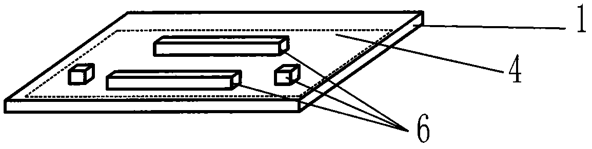
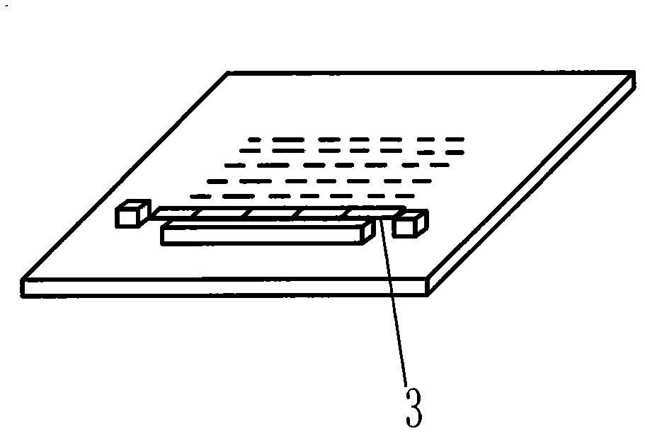
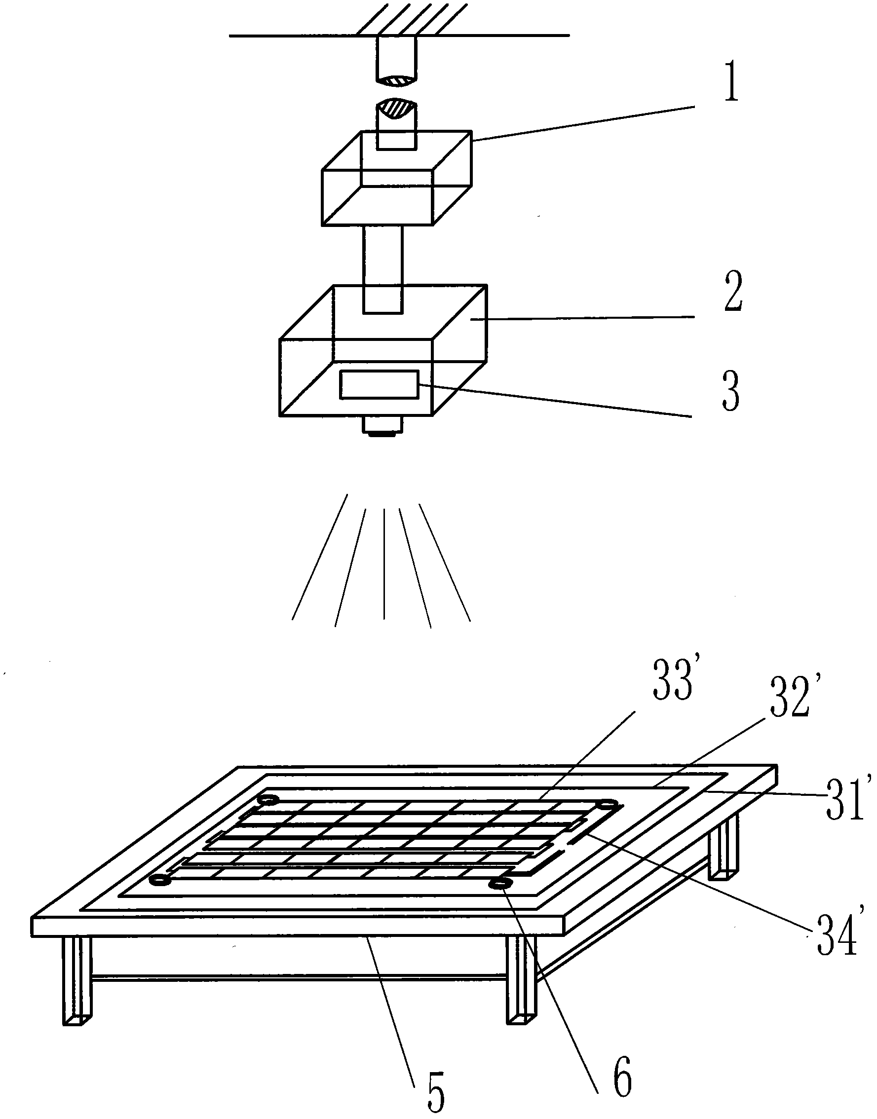
[0045] The embodiment of the present invention is used as figure 1 shown equipment Figure 5 The lamination of each layer of components in the shown solar cell module board, each layer of components is specifically:

[0046] ——The front top layer 1 is tempered glass;

[0047] - Both the front top adhesive layer 2 and the back adhesive layer 4 are ethylene-vinyl acetate copolymer films;

[0048] ——The back layer 5 is TPT;

[0049] ——The solar cell string array 3 includes multiple strings of solar cells connected by soldering strips 16 as conductive strips.

[0050] Such as figure 1 The equipment shown: the suspension adjustment device 1 fixed on the ceiling of the workshop is designed as a 3-axis adjustment mechanism such as the workbench of CNC machining equipment, which can electrically adjust the slide projector 2 to the right above the workbench 5 according to the appropriate height and orientation, and its projection With your head facing straight down, the image of ...


PUM


Abstract

The invention discloses a laminating method for a solar battery component panel manufacturing process, which comprises the steps as follows: solar cell series arrays and bottom layers or / and top layers of the solar cell series arrays are arranged on a supporting surface according to regulated sequence and location one by one. The laminating method for the solar battery component panel manufacturing process is characterized in that the invention also comprises a projector which receives graph information and projects the graph on the supporting surface; the graph information comprises the locating markers for placing the solar cell series arrays and the bottom layers or / and top layers of the solar cell series arrays; on the supporting surface, the solar cell series arrays and the bottom layers or / and top layers of the solar cell series arrays are arranged according to the locating markers and regulated sequence. The technical scheme avoids the influences of barrier caused by lamination layer by layer, is convenient to operate, has consistent locating references and higher precision, is convenient for production and design, and is convenient for production adjustment in particular.

Description

technical field [0001] The present invention relates to a lamination method for the manufacturing process of solar cell module panels, and in the International Patent Classification, the classification may belong to H01L31 / 18. Background technique [0002] At present, the components of each layer in the common solar cell module board are as follows: Figure 5 As shown, including front top layer 1, top layer adhesive layer 2, solar cell string array 3, back layer 5 and back layer adhesive layer 4, according to the following arrangement: [0003] ——Firstly, the front top layer is fixed on the working surface according to the specified position; then, [0004] - the front top adhesive layer is fixed on the front top layer in the specified position; then, [0005] ——The solar battery string array is fixed on the front top adhesive layer according to the specified position; after connecting the circuit, [0006] ——The adhesive layer of the back layer is fixed on the solar cell ...

Claims


Application Information

Patent Timeline
IPC IPC(8): H01L31/18
CPCY02P70/50
Inventor 王卫平
Owner 江门尚日新能源有限公司
Why Eureka
Try Eureka