Microprocessor with pipeline bubble detection device

A microprocessor and detection device technology, applied in machine execution devices, error detection/correction, electrical digital data processing, etc., can solve problems such as command rejection, and achieve the effects of avoiding pipeline bubbles, improving program codes, and saving costs

Inactive Publication Date: 2011-07-27
CONTINENTAL TEVES AG & CO OHG
View PDF3 Cites 0 Cited by
  • Summary
  • Abstract
  • Description
  • Claims
  • Application Information

AI Technical Summary

Problems solved by technology

However, if the branch prediction is incorrect, the commands executed in between must be rejected (pipeline flushing)

Method used


Image

  • Microprocessor with pipeline bubble detection device
  • Microprocessor with pipeline bubble detection device
  • Microprocessor with pipeline bubble detection device

Examples


Embodiment Construction

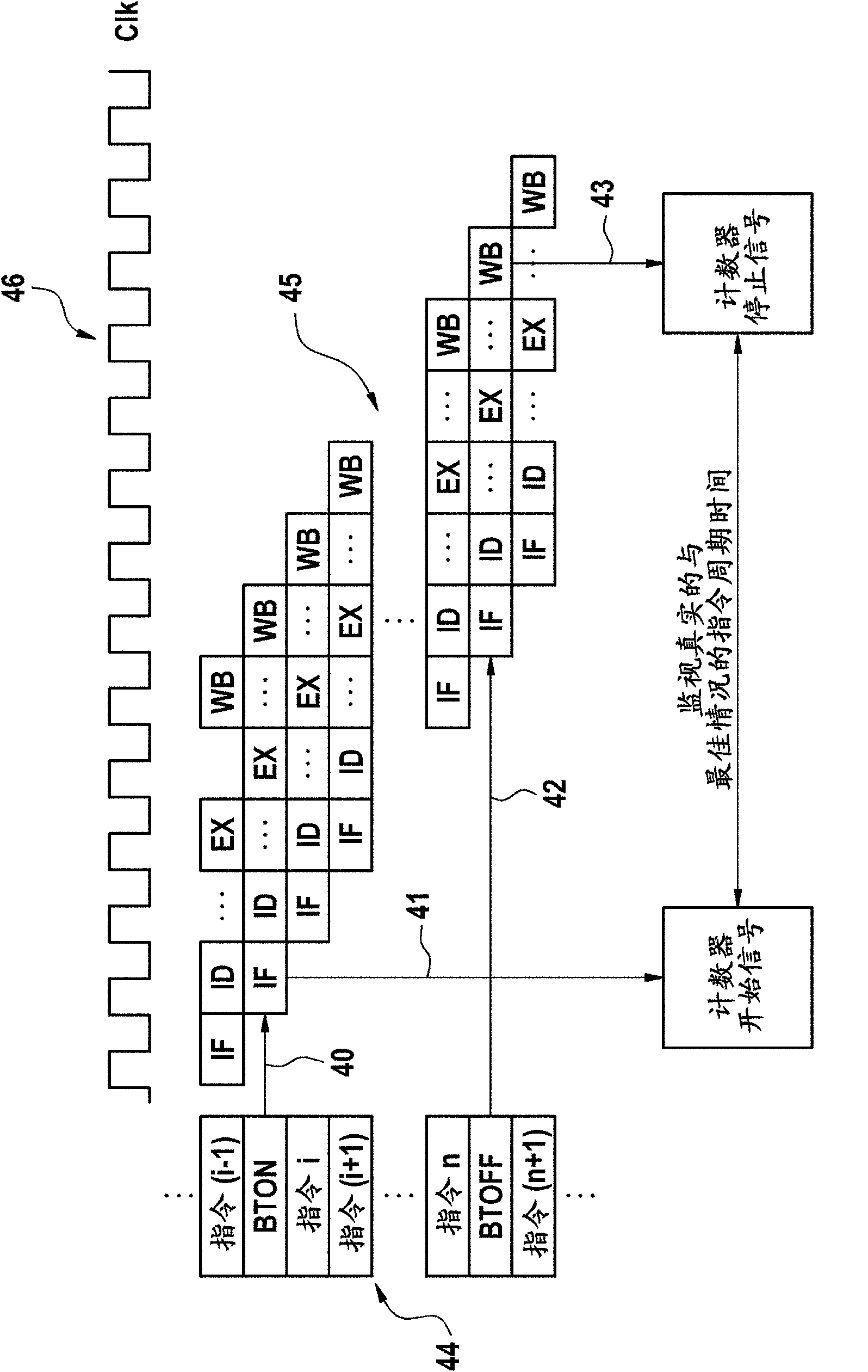
[0037] pass figure 1 The pipeline microarchitecture shown in the example in 1 includes various pipeline stages. Depending on the design of the pipeline microarchitecture, the number of stages can vary widely. For example, figure 1 The following pipeline stages are shown:

[0038] - IF (Instruction Fetch) stage 10 : The machine code or OP code 14 and associated data such as operands or destination addresses are fed to this pipeline stage via the input bus 15 .

[0039] - ID (Instruction Decode) stage 11 : In this stage 11 the commands are decoded when they are loaded or fetched.

[0040] - EX (execute) phase 12: After the command has been decoded and recognized, the command is executed.

[0041] - WB (Write Back) stage 13: In this stage the result is written back to the registers eg via the pipeline output bus 16 and possibly kept ready for further execution steps.

[0042] The pipeline microarchitecture 1 is connected to the pipeline foam detection device 2 . Commands ex...


PUM


Abstract

The present invention discloses a microprocessor, comprising a pipeline microarchitecture (1) and a pipeline bubble detection device (2), wherein the pipeline bubble detection device (2) comprises a minimum processing timing cycle determination unit (3) for determining a minimum and / or optimum number of processing timing cycles of one or more program commands, said cycles running through the pipeline microarchitecture (1) and / or being processed thereby.

Description

technical field [0001] The invention relates to a microprocessor according to the preamble of claim 1 , a method for activating a microprocessor according to the preamble of claim 8 , and the use of the microprocessor in a motor vehicle. Background technique [0002] Pipelined microarchitecture, or pipelining, is a known way of increasing the performance of processing cores in microprocessors. In this case, the execution of machine commands is decomposed into successive units of tasks that execute overlappingly. Such overlapping can increase throughput during execution of program commands or machine commands. The number of commands executed per clock cycle or clock unit can be further increased by extending the capabilities of the pipeline. One possible extension is provided by, for example, superscalar techniques. Such techniques rely on dynamic allocation of functional units for the simultaneous transfer of multiple machine commands from command sequences to parallel op...

Claims


Application Information

Patent Timeline
Patent Type & Authority Applications(China)
IPC IPC(8): G06F9/30G06F9/38G06F11/34
CPCG06F9/30145G06F9/30003G06F9/3869G06F11/348
Inventor A·基施鲍姆L·D·卡布莱帕
Owner CONTINENTAL TEVES AG & CO OHG
Why Eureka
Try Eureka