Three-phase separator of efficient anaerobic bioreactor

A three-phase separator and anaerobic biological technology, applied in the field of wastewater treatment, can solve the problems such as the inability to effectively separate small granular sludge and flocculent sludge, affecting the effluent quality and subsequent treatment process, and reducing the treatment efficiency of the reactor. , to achieve the effect of avoiding sludge loss, simple structure, and enhanced resistance to load impact.

Active Publication Date: 2012-11-21
北京杰佳洁环境技术有限责任公司 +1
View PDF0 Cites 5 Cited by
  • Summary
  • Abstract
  • Description
  • Claims
  • Application Information

AI Technical Summary

Problems solved by technology

[0003] The gas collection hood of the traditional three-phase separator is mostly double-layered. When the mixed liquid passes through the backflow gap between the gas collection hoods, due to the smaller cross-sectional area and the increase of the upward flow velocity, the impact will fall back to the sludge in the reaction zone. As a result, the separation efficiency is reduced, and a small amount of small particle sludge and flocculent sludge cannot be effectively separated, which will lead to the loss of this part of the sludge, affecting the quality of effluent water and subsequent treatment processes
In order to ensure the separation efficiency, it is necessary to reduce the rising flow rate of the mixed liquid, which will lead to a decrease in the processing efficiency of the reactor.
[0004] The gas collecting hood of the ordinary three-phase separator is generally installed horizontally, and is connected to the biogas storage room through the gas pipe, which is not conducive to the collection of biogas
[0005] In addition, ordinary three-phase separators need to be installed one by one on site, and the installation accuracy cannot be guaranteed, and air leakage and mud running may occur from time to time, which reduces the separation efficiency and increases the project cost

Method used


Image

  • Three-phase separator of efficient anaerobic bioreactor

Examples


Embodiment Construction

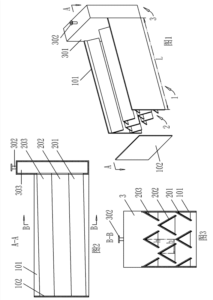
[0023] refer to figure 1 , figure 2 As shown, a three-phase separator for an efficient anaerobic bioreactor mainly includes components such as a three-phase separator box 1, a gas collection hood 2, and a biogas storage chamber 3; the three-phase separator box 1 is up and down An open rectangular structure with a length of 4900mm, a width of 1900mm, and a height of 1800mm. The material is made of polyester fiberglass. One end of the side plates 101 of the box body 1 is fixedly connected with the outer shell 301 of the rectangular biogas storage room 3, and the other end is connected with the box The body sealing plate 102 is fixedly connected, and the top of the biogas storage chamber 3 is provided with an air outlet 302; the gas collecting hood 2 is integrally formed by a mold at one time, and there is no air leakage.

[0024] Also refer to image 3 As shown, the described three-phase separator box 1 is equipped with multi-layer angle steel 103, and multi-layer angle steel...


PUM


Abstract

The invention relates to a three-phase separator of an efficient anaerobic bioreactor, comprising a three-phase separator box body and gas collecting hoods, wherein the three-phase separator box body is internally provided with a plurality of the gas collecting hoods; one ends of two side plates of the three-phase separator box body are connected with a marsh gas storage chamber so as to prevent sludge loss, reduce influences on a subsequent treatment process and furthest collect a marsh gas by effectively separating granular sludge, flocculent sludge and the marsh gas which are contained in a mixed solution; the marsh gas storage chamber is directly communicated with the gas collecting hoods so as to solve the problem of easy blockage caused in such a way that a pipeline is used for connection; the gas collecting hoods have certain installation slopes so as to be beneficial to the collection of the separated marsh gas into the marsh gas storage chamber; and the collected marsh gas exhausted from a gas outlet positioned on the top end of the marsh gas storage chamber can be recovered to be used for marsh gas power generation or purified to be used as a natural gas. The three-phaseseparator can be conveniently integrally arranged in the efficient anaerobic bioreactor, not only ensures the accuracy of equipment, but also more enhances the quality of outflow water without gas leakage or sludge loss, enhances the separating efficiency and also reduces the construction cost.

Description

technical field [0001] The invention belongs to the technical field of waste water treatment and relates to a three-phase separator for high-efficiency anaerobic bioreactors used for treating medium- and high-concentration organic waste water. Background technique [0002] The function of the three-phase separator in the anaerobic bioreactor is to separate the gas, liquid and solid mixture rising from the reaction zone. The separation effect directly affects the quality of the effluent water, the concentration of sludge in the reactor and the collection of biogas. The key to success or failure. [0003] The gas collection hood of the traditional three-phase separator is mostly double-layered. When the mixed liquid passes through the backflow gap between the gas collection hoods, due to the smaller cross-sectional area and the increase of the upward flow velocity, the impact will fall back to the sludge in the reaction zone. As a result, the separation efficiency is reduced,...

Claims


Application Information

Patent Timeline
Patent Type & Authority Patents(China)
IPC IPC(8): C02F3/28
CPCY02E50/30
Inventor 唐一
Owner 北京杰佳洁环境技术有限责任公司
Why Eureka
Try Eureka