

Multi-needle sewing machine
A sewing machine and needle type technology, applied in the field of needle bar housing moving mechanism, can solve problems such as difficulty in threading operations, and achieve the effects of preventing thread interlacing, inexpensive structure, and stable action
- Summary
- Abstract
- Description
- Claims
- Application Information
AI Technical Summary
Problems solved by technology
Method used
Image

Examples
no. 1 approach
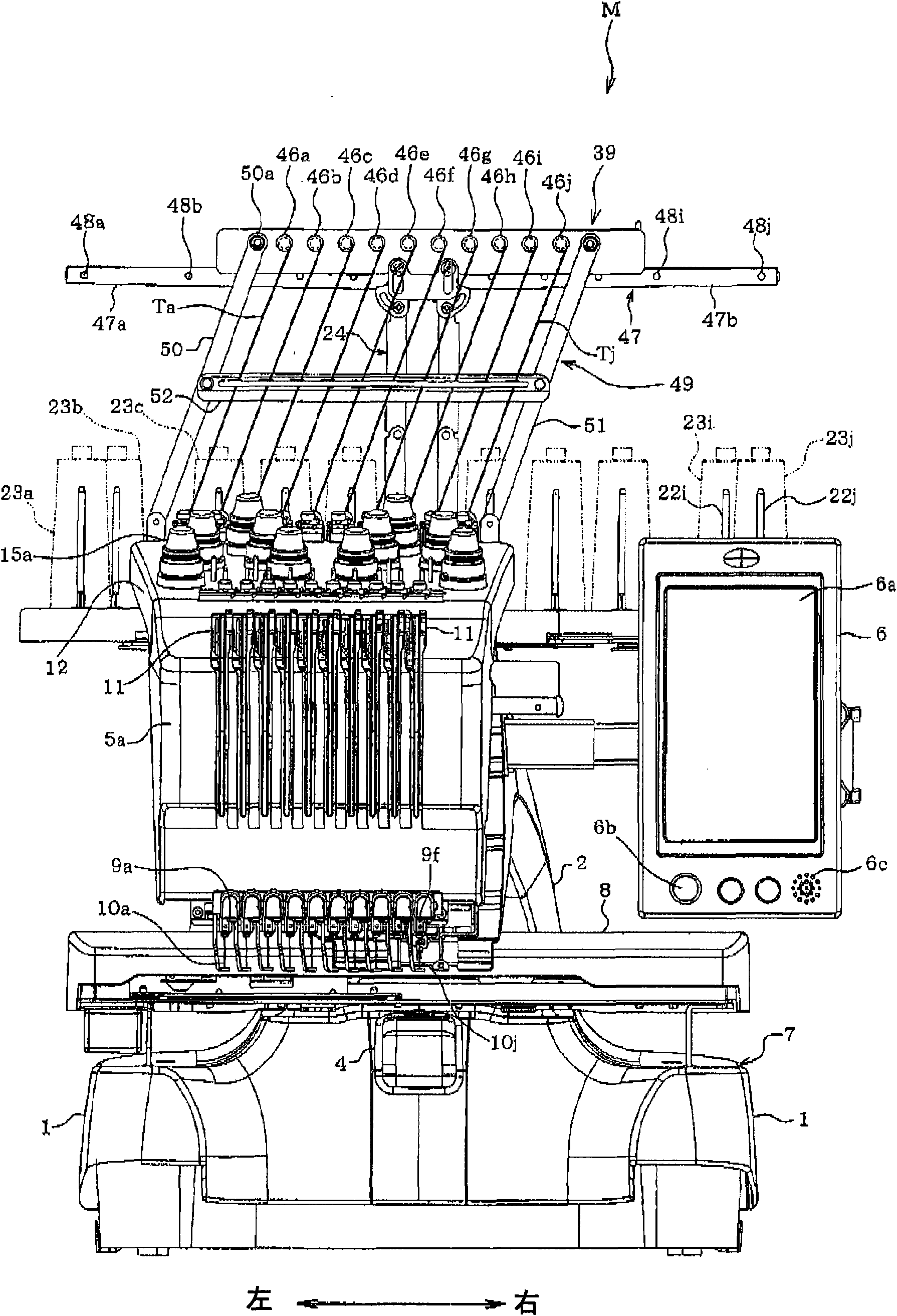
[0056] Refer below Figure 1 to Figure 26 A first embodiment in which the present invention is applied to a multi-needle embroidery sewing machine (hereinafter referred to as a multi-needle sewing machine M) will be described. figure 1 It is a front view of the multi-needle sewing machine M, and the direction in which the user is located (the outside of the drawing) will be described as the front.
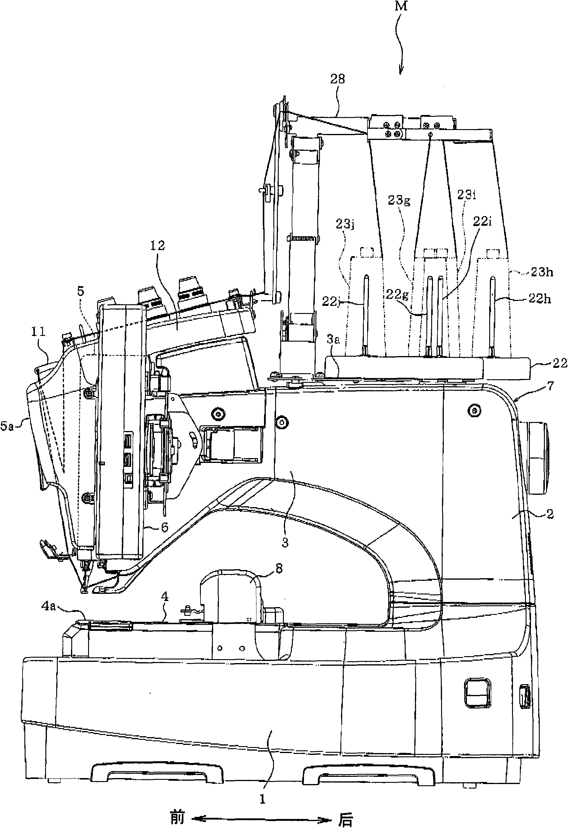
[0057] Such as Figure 1 to Figure 4 As shown, the multi-needle sewing machine M includes: a pair of left and right leg parts 1 supporting the whole sewing machine, a column part 2 erected from the rear end of the leg part 1, and an arm part 3 extending forward from the upper part of the column part 2. , a cylindrical base 4 extending forward from the lower end of the column part 2, a needle bar housing 5 mounted on the front end of the arm part 3 (refer to figure 2 , Figure 6 ).
[0058] The leg portion 1 , the column portion 2 , the arm portion 3 , and the cylindrical base ...
no. 2 approach
[0120] Figure 27 ~ Figure 30 The second embodiment of the present invention is shown. The second embodiment differs from the first embodiment in the structure of the support column 70, the vertical movement mechanism 71, and the like. The strut 70 is composed of, for example, a single columnar member with a U-shaped cross section, a square pipe or a circular pipe, or the like. On the mounting piece portion 40k of the wire guide member 39, the elongated holes 43A', 43B' are formed in a line in the longitudinal direction. The wire guide member 39 is vertically movably provided on the upper end of the post 70 by inserting the stepped screws 38A, 38B through the elongated holes 43A′, 43B′ and screwing them into unshown screw holes of the post 70 .
[0121] The vertical movement mechanism 71 includes a vertical movement motor 72 , a rack 73 , a pinion 74 , and a control device 75 . The vertical motion motor 72 corresponds to an actuator, and is constituted by, for example, a pe...
no. 3 approach
[0130] Figure 31 ~ Figure 34 The third embodiment of the present invention is shown. In the first embodiment, the support 24 adopts a fixed support structure in which each constituent member is finally fixed (while the sewing machine is in operation) in a fixed manner. The strut 80 of the third embodiment uses the same constituent members as the strut 24 . A detailed description of each constituent member is omitted. When the elongated holes 43A, 43B of the wire guide member 39 of the first embodiment are not formed, the wire guide member 39 is fixed to the upper end portion of the strut 80 , that is, the upper support portion mounting pieces 31A, 31B of the upper support body portion 28 .
[0131] The strut 80 has the same constituent members as the strut 24 , but its function during use is different. That is, the strut 80 has a structure in which the screws 35A and 35B of the first embodiment are removed. Therefore, the upper pillar portions 27A, 27B are swingable abou...
PUM
 Abstract
Description
Claims
Application Information