
Multi-layer inner flame combustor and gas cooker with same

A burner and inner cavity technology, applied in the field of gas stoves, can solve the problems of difficulty in further optimizing the size of the main body of the fire distributor, limitations in the promotion and application of multi-layer inner flame burners, unfavorable burner structure size, etc., to increase heat exchange The area and heat exchange time are conducive to popularization and application, and the effect of energy saving is remarkable.

Active Publication Date: 2013-03-20
MIDEA GRP CO LTD
View PDF2 Cites 0 Cited by
  • Summary
  • Abstract
  • Description
  • Claims
  • Application Information

AI Technical Summary

Problems solved by technology

The main body of the fire distributor is usually formed by forging. In order to meet the requirements of the forging process, the structural size of the main body of the fire distributor is difficult to further optimize, and it involves the optimization of the structural size of the entire burner.
In addition, the material of the main body of the burner that cooperates with the main body of the fire distributor is also limited by the temperature resistance of the material at the fire hole not lower than 700°C
It is precisely because of the limitation of the material at the fire hole that the production cost of this patent is high, and the optimization of the burner structure size is limited; at the same time, due to the limitation of the fire hole cross-section in this patent, its application range is limited
[0005] In summary, the current multi-layer inner flame burner and the gas stove equipped with multi-layer inner flame burner, because the burner fire hole is designed on the main body of the fire distributor, and the cross section of the fire hole is limited, not only increases the The manufacturing cost of the burner is not conducive to the optimization of the structure size of the burner, and limits the popularization and application of the multi-layer internal flame burner

Method used


Image

  • Multi-layer inner flame combustor and gas cooker with same
  • Multi-layer inner flame combustor and gas cooker with same
  • Multi-layer inner flame combustor and gas cooker with same

Examples


Embodiment 1

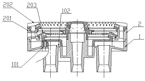
[0040] Such as figure 1 As shown, the present embodiment is an upper-intake multi-layer internal flame burner, which includes a burner body 1 and a fire distributor device 2, and the burner body and the fire distributor device are combined together by a cylindrical surface and a plane; the burner body is The upper air inlet structure; the fire distributor device is composed of the fire distributor main body 201, the upper fire cover 202, and the lower fire cover 203. The inner cavity of the fire distributor main body is connected with the inner cavity of the burner main body; The main body has several screw holes 101 at the position corresponding to the lower fire cover, and is provided with a mounting plane 102 corresponding to the lower fire cover; through screws, the lower fire cover is connected with the fire distributor main body and the burner main body.

[0041] Such as figure 2 As shown, the main body 201 of the fire distributor is provided with a separation layer 201...

Embodiment 2

[0045] This embodiment is except following feature, and other is all identical with embodiment 1:

[0046] Such as Figure 7 As shown, this embodiment is a multi-layer internal flame burner with downward air intake, which includes a burner body 1 and a flame distributor device 2, and the burner body 1 and the flame distributor device 2 are combined together by a cylindrical surface; the burner body It is a lower air intake structure, and there is no screw hole 101 on the burner body; the inner wall section of the lower fire cover 203 ( Figure 8 In 203.8) there is no inwardly protruding arc section 203.3, and there is no inner cavity 203.6 formed by the arc section; the lower fire cover passes through the inner wall section 203.8, the outer cylindrical section 203.9 and the main body of the fire distributor and the burner. The main body snaps together.

Embodiment 3

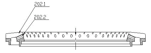
[0048] There is no figure in this embodiment, refer to the related figure of embodiment 1. Except that the setting of the fire hole of the upper fire cover is different from that of Example 1, all the others are the same as that of Example 1. The difference is that there are dozens of strip-shaped fire holes 202.1 on the top of the upper fire cover (the number of fire holes can be determined according to actual needs); there are two circles of circular fire holes on the inner conical surface of the upper fire cover (according to actual needs). Determine the number of fire holes), and two circles of circular fire holes are evenly distributed along the circumference.


PUM


Abstract

The invention discloses a multi-layer inner flame combustor and a gas cooker with the same. The multi-layer inner flame combustor comprises a combustor main body 1 and a distributor device 2, wherein the combustor main body is combined with the distributor device together through a cylindrical surface, a circular conical surface or a flat surface; the combustor main body has an upper wind inlet structure; the distributor device consists of a distributor main body 201, an upper flame cover 202 and a lower flame cover 203; the distributor main body is not provided with a flame hole and is molded by pressure casting through an aluminum alloy material; the upper flame cover is arranged at the upper end of the distributor main body; a plurality of screw holes 101 and an installation surface 102 corresponding to the lower flame cover are formed at the position of the combustor main body corresponding to the lower flame cover; and the lower flame cover is integrally connected with the distributor main body and the combustor main body through screws. In the combustor and the gas cooker, a plurality of layers of inner flames are subjected to layered combustion and segmentation oxygen supplementation to form cubic flames which are spatially distributed in a staggered way, low CO and NO emission is realized, and obvious effects of energy saving and environmental friendliness are achieved.

Description

technical field [0001] The invention relates to the field of gas stoves, in particular to a multilayer inner flame burner and a gas stove equipped with a multilayer inner flame burner. Background technique [0002] The development of gas stoves has paid more and more attention to "energy saving and environmental protection"; the inner flame gas stove has been widely concerned by people because of its remarkable energy-saving effect. [0003] One of the inventions disclosed in the Chinese invention patent "a burner for an inner-flame gas stove" (patent number: 200710305041.1, authorized announcement number: CN101403500B) is as follows: a burner for an inner-flame gas stove, which consists of a burner body and a Composed of a fire distributor device, the burner body includes a burner head and a central fire cover, and the fire distributor device includes a fire distributor body and a fire distributor top cover, and the burner body and the fire distributor device are combined b...

Claims


Application Information

Patent Timeline
Patent Type & Authority Patents(China)
IPC IPC(8): F23D14/00F23D14/84
Inventor 吴成年方松青周强
Owner MIDEA GRP CO LTD
Learn More