35kV shielding type separable connector and expansion method thereof

A separate connector and shielding type technology, applied in the direction of connection, conductive connection, electrical component connection, etc., can solve problems such as insufficient insulation strength, strict installation process requirements, deformation of the front and rear insertion interfaces, etc., to avoid uneven spraying and conductive Good performance, the effect of improving electrical performance

Active Publication Date: 2011-08-03
GCA CO LTD
View PDF6 Cites 3 Cited by
  • Summary
  • Abstract
  • Description
  • Claims
  • Application Information

AI Technical Summary

Problems solved by technology

There are two main expansion methods for the existing shielded separable connectors with a voltage level of 30kV and below: one is to directly use the rear plug-in separable connector to connect to the front plug-in separable connector, so as to The expansion of the detachable connector is realized, but when this structure is used in a 35kV system, the detachable connector has very strict requirements on the installation method and installation environment, otherwise it is very easy to deform the front and rear plug interfaces due to the installation of the rear plug and cause air leakage. gap, resulting in unstable overall performance; the other is to use epoxy double-pass bushing as the intermediate connector. The shortcomings of this epoxy bushing structure are limited flow capacity, insufficient insulation strength, and strict requirements on the installation process. And it

Method used


Image

  • 35kV shielding type separable connector and expansion method thereof
  • 35kV shielding type separable connector and expansion method thereof
  • 35kV shielding type separable connector and expansion method thereof

Examples


Example Embodiment

[0034] Example one

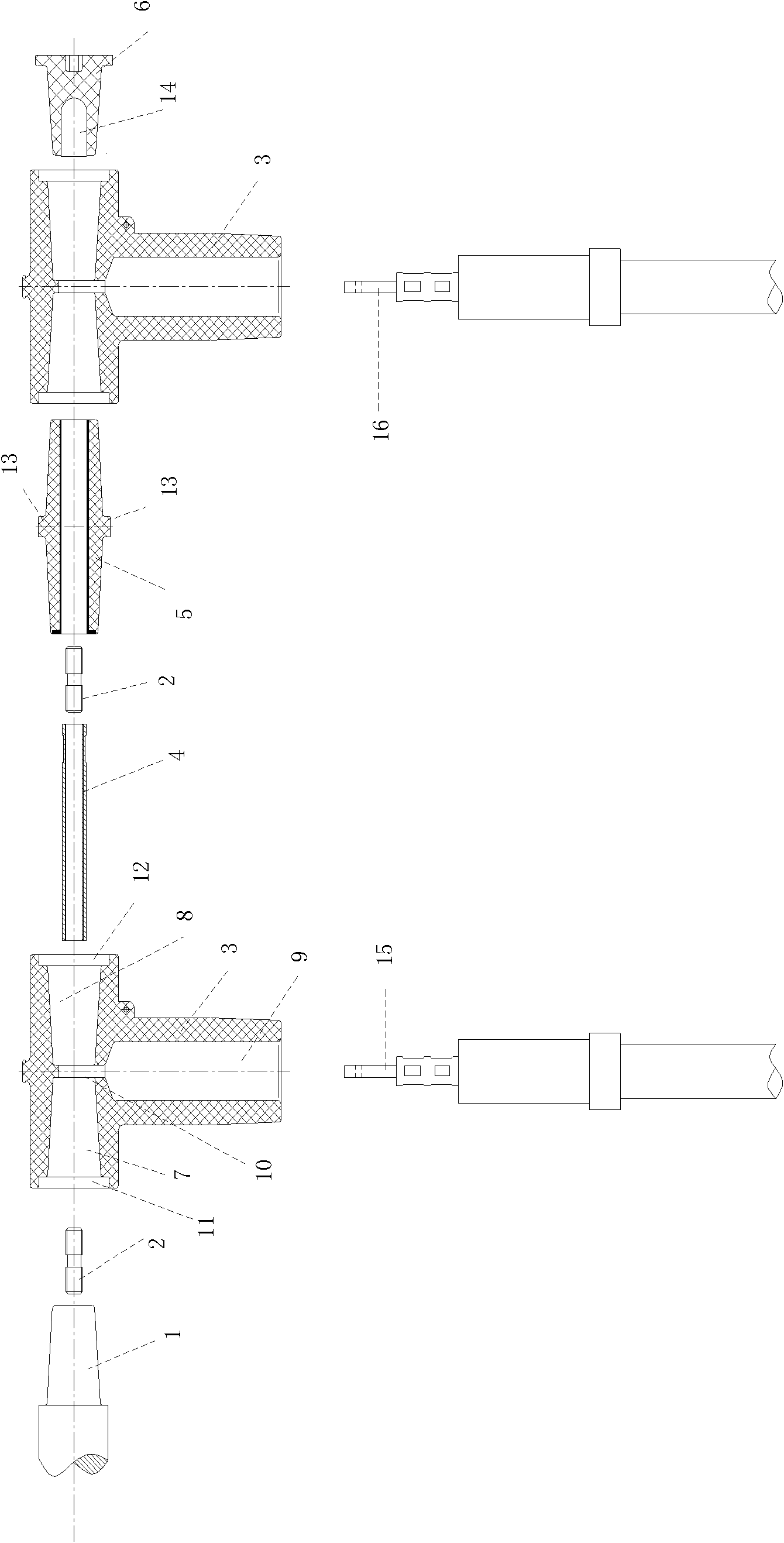
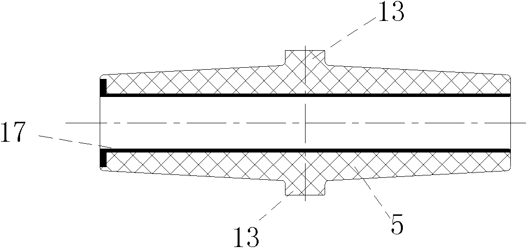
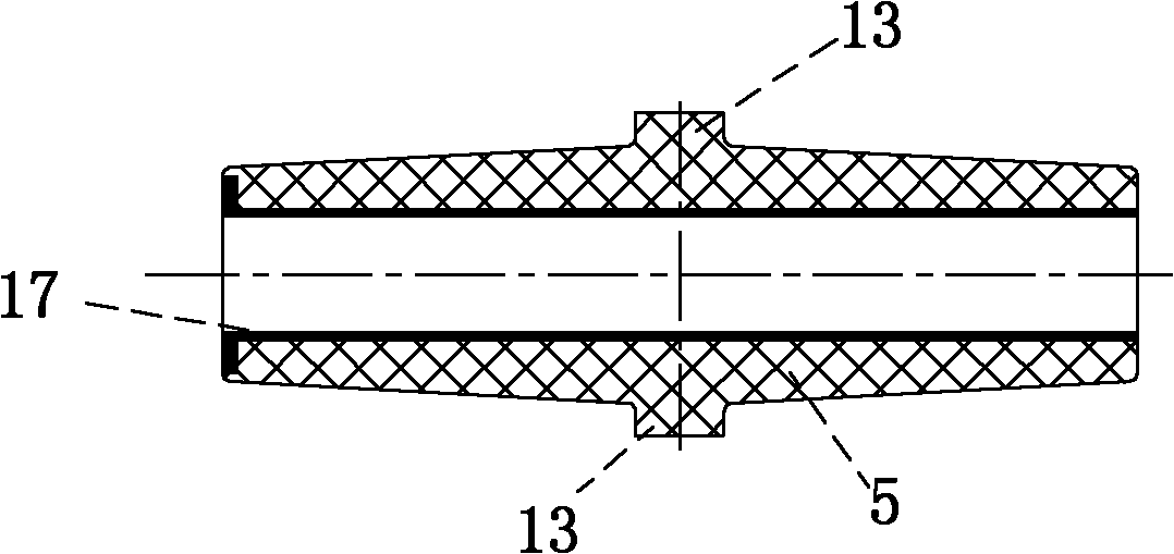
[0035] The exploded view of the 35kV shielded separable connector of the present invention for two-level expansion is as figure 1 As shown, it includes two identical "T"-shaped separable connectors 3 and an intermediate connector, which connects two "T"-shaped separable connectors; the horizontal part of the "T"-shaped separable connector 3 A first cavity 7 and a second cavity 8 that are connected to each other and have the same shape are provided along the horizontal direction. The first cavity 7 and the second cavity 8 penetrate the horizontal part and the vertical part of the "T"-shaped separable connector A third cavity 9 is arranged in the vertical direction. The "T"-shaped separable connector is symmetrical with respect to the longitudinal axis of the third cavity 9; the "T"-shaped separable connector is prefabricated with a conductive unit 10, the conductive unit 10 is arranged between the first cavity and the second cavity, and communicates with the t...

Example Embodiment

[0044] Example two

[0045] The 35kV shielded separable connector of the present invention can also be used for multi-level expansion. The specific steps are as follows:

[0046] In the first step, a cable is inserted into the third cavity of all "T"-shaped separable connectors, and the cable is inserted into the conductive unit through the conductive terminal;

[0047] The second step is to connect the first cavity of a "T"-shaped separable connector to the switch cabinet bushing, and connect a conductive rod to the switch cabinet conductor through the connector;

[0048] In the third step, insert the left end of the insulating jacket from the second cavity of the "T"-shaped separable connector in the second step and cover it outside the conductive rod;

[0049] In the fourth step, put the first cavity of a "T"-shaped separable connector into the right end of the newly connected insulating jacket, and connect another conductive rod with the newly connected conductive rod through the co...


PUM

PropertyMeasurementUnit
Thicknessaaaaaaaaaa

Abstract

The invention relates to a 35kV shielding type separable connector, comprising at least two same T-shaped separable connectors and at least one middle connector, wherein horizontal parts of the T-shaped separable connectors are provided with first cavity bodies and second cavity bodies which are mutually communicated, and vertical parts of the T-shaped separable connectors are provided with third cavity bodies along the vertical direction; the T-shaped separable connectors are in bilateral symmetry relative to the longitudinal axes of the third cavity bodies; conducting units are prefabricated in the T-shaped separable connectors, are arranged among the first cavity bodies and the second cavity bodies and are communicated with the third cavity bodies; the middle connector comprises insulating jackets and a hollow conducting rod sheathed in the insulating jackets; the insulating jackets are in bilateral symmetry, and the left half part and the right half part are respectively adaptive to the first cavity bodies and the second cavity bodies; and the two ends of the conducting rod are respectively and fixedly connected with a connecting piece. In the 35kV shielding type separable connector, the electric performance effect is good, the multi-stage expansion can be realized, and the expansion method is used for connecting the plurality of T-shaped separable connectors in series.

Description

technical field [0001] The invention relates to a power cable accessory, in particular to a 35kV outer cone separable connector and an extension method thereof. Background technique [0002] The connector is suitable for the incoming and outgoing line terminals of the ring network switchgear, connected with the insulating seat of the switch, and also suitable for various cable branch boxes and box-type substation devices. With the transformation and expansion of urban power grids, higher requirements are placed on separable connectors. There are two main expansion methods for the existing shielded separable connectors with a voltage level of 30kV and below: one is to directly use the rear plug-in separable connector to connect to the front plug-in separable connector, so as to The expansion of the detachable connector is realized, but when this structure is used in a 35kV system, the detachable connector has very strict requirements on the installation method and installati...

Claims


Application Information

Patent Timeline
IPC IPC(8): H01R11/00H01R13/02H01R13/514H01R13/648H01R4/56H01R24/00H01R43/00
Inventor 陈朝晖张金梅候琦
Owner GCA CO LTD
Why Eureka
Try Eureka