
Solar cell power supply device and rechargeable battery solar charging method

A technology of solar cells and power supply devices, which is applied in secondary battery charging/discharging, battery circuit devices, secondary battery repair/maintenance, etc., and can solve problems such as difficulty in charging, incapable capacity, and reduced capacity

Inactive Publication Date: 2011-08-03
SANYO ELECTRIC CO LTD
View PDF7 Cites 17 Cited by
  • Summary
  • Abstract
  • Description
  • Claims
  • Application Information

AI Technical Summary

Problems solved by technology

However, if the timing of blocking the charging current is too early, the charging will be completed in the state of not being fully charged, and the capacity that can be taken out from the secondary battery will be reduced, so that the original capacity cannot be exerted.
In this way, in a conventional power supply unit that combines a solar cell and a secondary battery, it is difficult to charge the secondary battery to fully exhibit its performance.

Method used


Image

  • Solar cell power supply device and rechargeable battery solar charging method
  • Solar cell power supply device and rechargeable battery solar charging method
  • Solar cell power supply device and rechargeable battery solar charging method

Examples


Embodiment 1

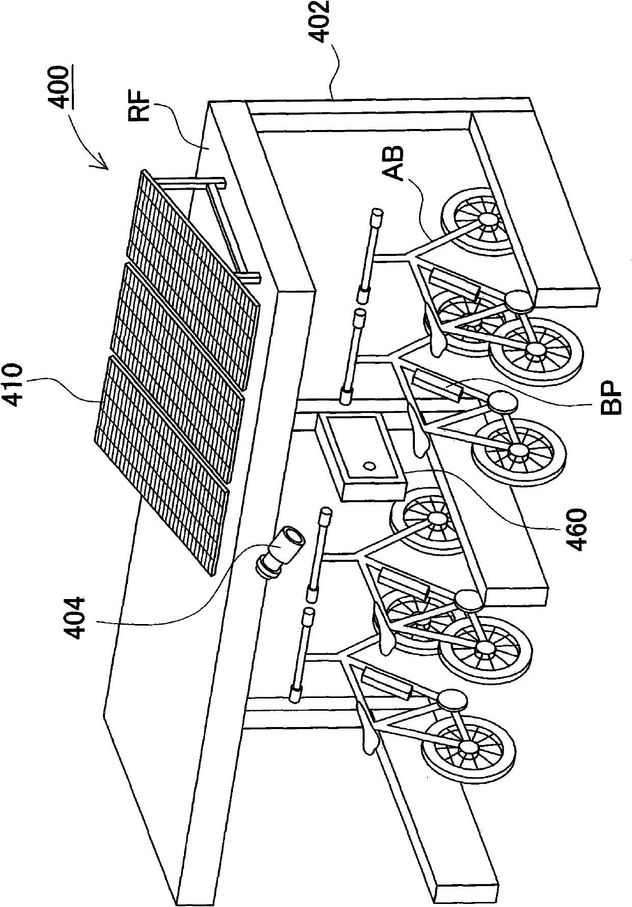
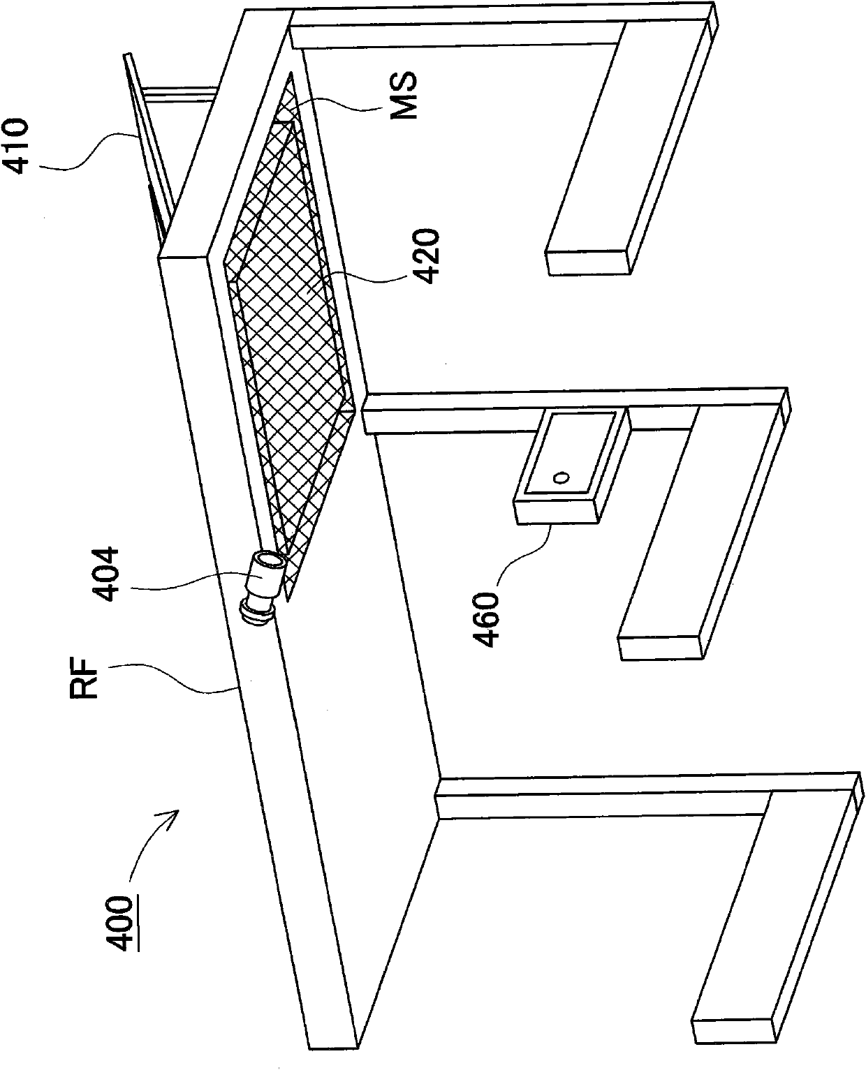
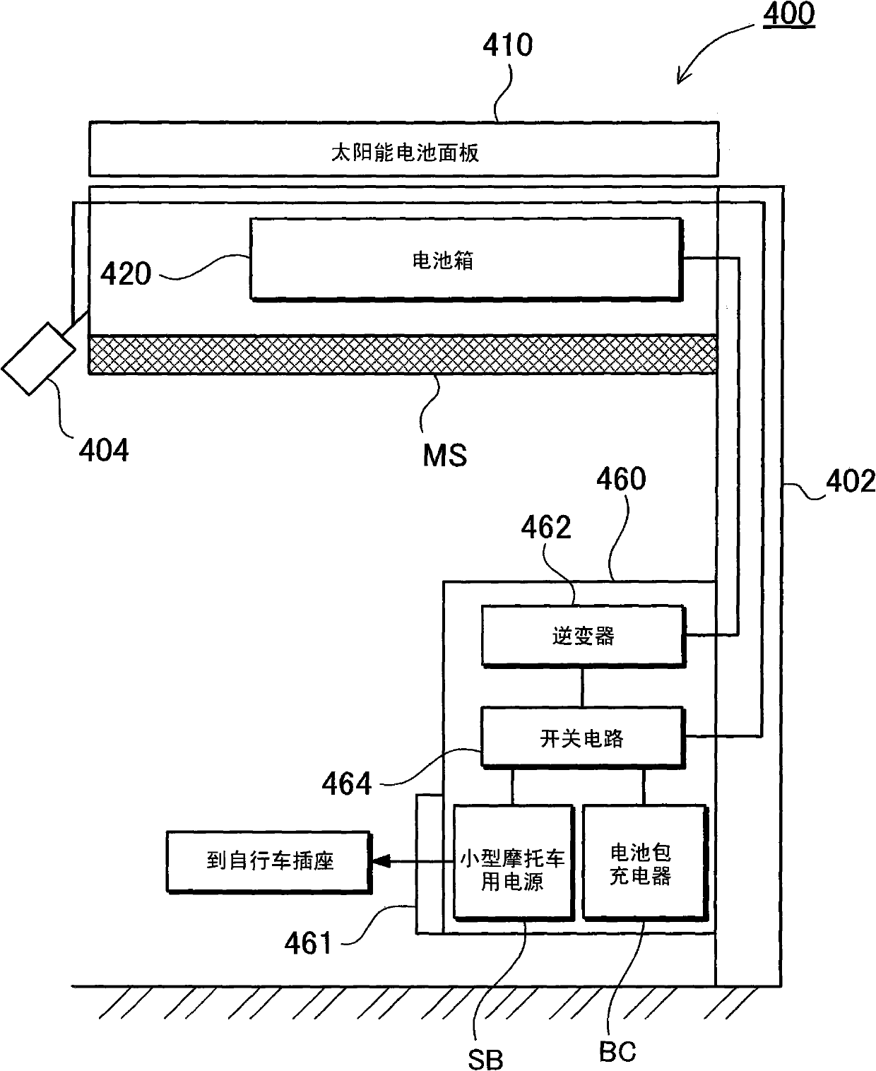
[0060] Figure 1 to Figure 20 A solar cell power supply device 400 according to Embodiment 1 of the present invention is shown. In these figures, the following are represented respectively: figure 1 It is a schematic diagram illustrating an example of applying a solar battery power supply unit to a charging facility at a bicycle parking place; figure 2 is a schematic diagram of the roof of the bike park seen from below; image 3 yes means figure 1 A block diagram of the structure of the solar cell power supply device; Figure 4 is a schematic diagram of the front of the console; Figure 5 is a perspective view of the appearance of the battery box seen from above; Image 6 is seen from below Figure 5 A three-dimensional view of the battery box; Figure 7 From Figure 5 An exploded perspective view of the state after the upper shell is removed; Figure 8 Yes Figure 5 Sectional view of line VIII-VIII; Figure 9 It is an exploded perspective view showing a state wh...

Embodiment 2

[0129] (Example 2 street lamp)

[0130] In the first embodiment above, an example of using the solar battery power supply device 400 to add the charging function of the battery pack to the bicycle parking place is described, but the load connected to the solar battery power supply device is not limited to this example, and various electrical equipment can be connected. Below, based on Figure 21 ~ Figure 31 , as Embodiment 2, an example of a solar cell power supply device 100 using a street lamp as a load will be described. In these figures, the following are represented respectively: Figure 21 It is a perspective view of the appearance of the solar battery power supply device seen from the front side; Figure 22 is a perspective view seen from the back side; Figure 23 From Figure 22 A perspective view of the state where the battery cover is removed to expose the battery box; Figure 24is a perspective view of the appearance of the battery box seen from obliquely above...


PUM


Abstract

The present invention provides a solar cell power supply device and a rechargeable battery solar charging method. The solar cell power supply device is provided with a battery pack connected in series or in parallel with a plurality of rechargeable cells; a solar cell panel having a plurality of solar cells for generating power to charge the battery pack; a charging control portion capable of controlling charging current or charging voltage when the battery pack is charged by the power generated by the solar cell panel; a current detecting portion for detecting charging current of the battery pack; and a voltage detecting portion for detecting battery voltage of the battery pack. The charging control portion is configured to, when the battery pack is brought close to the fully-charged state, cuts off the charging current at predetermined timing for a charging operation stop period, and compare the battery voltage of the battery pack with a predetermined voltage value as a restart voltage value in the charging operation stop period. The charging control portion determines that the battery pack is fully charged if the battery voltage of the battery pack is not less than the predetermined voltage value as the restart voltage value, and cuts off the charging current.

Description

technical field [0001] The present invention relates to a solar battery power supply device capable of storing and utilizing power generated by sunlight in a secondary battery and a charging method of a secondary battery using a solar battery, and particularly relates to a method capable of directly charging a secondary battery without using a DC / DC converter. A solar cell power supply device that connects a solar cell and a secondary battery to stably charge the secondary battery from the solar cell, and a charging method for the secondary battery using the solar cell. Background technique [0002] Considering CO 2 In order to reduce environmental problems such as reduction, a power supply system that stores and utilizes electric power generated using natural energy that does not depend on fossil fuels has been proposed (for example, refer to Patent Document 1). In this power system, such as Figure 35 As shown, the solar cell and the secondary battery are connected via a ...

Claims


Application Information

Patent Timeline
Patent Type & Authority Applications(China)
IPC IPC(8): H02J7/00H01M10/44
CPCH02J7/35Y02T90/12H02J7/355Y02E10/566H02J7/0027H02J7/045B60L2230/22H02J7/008B60L53/51Y02T10/7072Y02T10/70H02J7/04H02J7/0045H02J7/0014H02J7/007182H02J2310/48Y02E10/56
Inventor 三野孝之森名贤一栗原俊武
Owner SANYO ELECTRIC CO LTD
Learn More