
Distributed safety monitoring system provided with a safety loop and method of testing such a system

A safety monitoring, distributed technology, used in electronic circuit testing, circuit breaker testing, electronic protection circuit testing, etc.

Inactive Publication Date: 2011-08-03
BOMBARDIER TRANSPORTATION GMBH
View PDF7 Cites 8 Cited by
  • Summary
  • Abstract
  • Description
  • Claims
  • Application Information

AI Technical Summary

Problems solved by technology

While effective when only one main relay needs to be monitored, this device is difficult to use in a safety circuit that includes multiple safety relays in series with the common supply

Method used


Image

  • Distributed safety monitoring system provided with a safety loop and method of testing such a system
  • Distributed safety monitoring system provided with a safety loop and method of testing such a system
  • Distributed safety monitoring system provided with a safety loop and method of testing such a system

Examples


Embodiment Construction

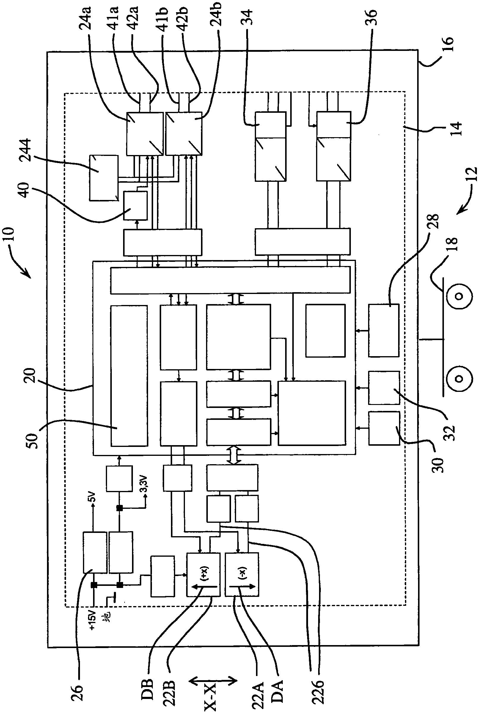
[0055] refer to figure 1 , an instability monitoring device 10 dedicated to monitoring the instability of a bogie 12 includes a printed circuit board 14 mounted in a box 16 secured to a bogie frame 18 . The printed circuit board 14 is built around a programmable logic device (PLD) 20 that includes two identical lateral accelerometers 22A, 22B as primary inputs, and two solid state safety relays as primary outputs 24a, 24b. In addition to the necessary power supply circuit 26, the system is equipped with a temperature sensor 28, a clock circuit 30, a watchdog circuit 32, an input 34 for test commands and an output 36 for indicating instability.

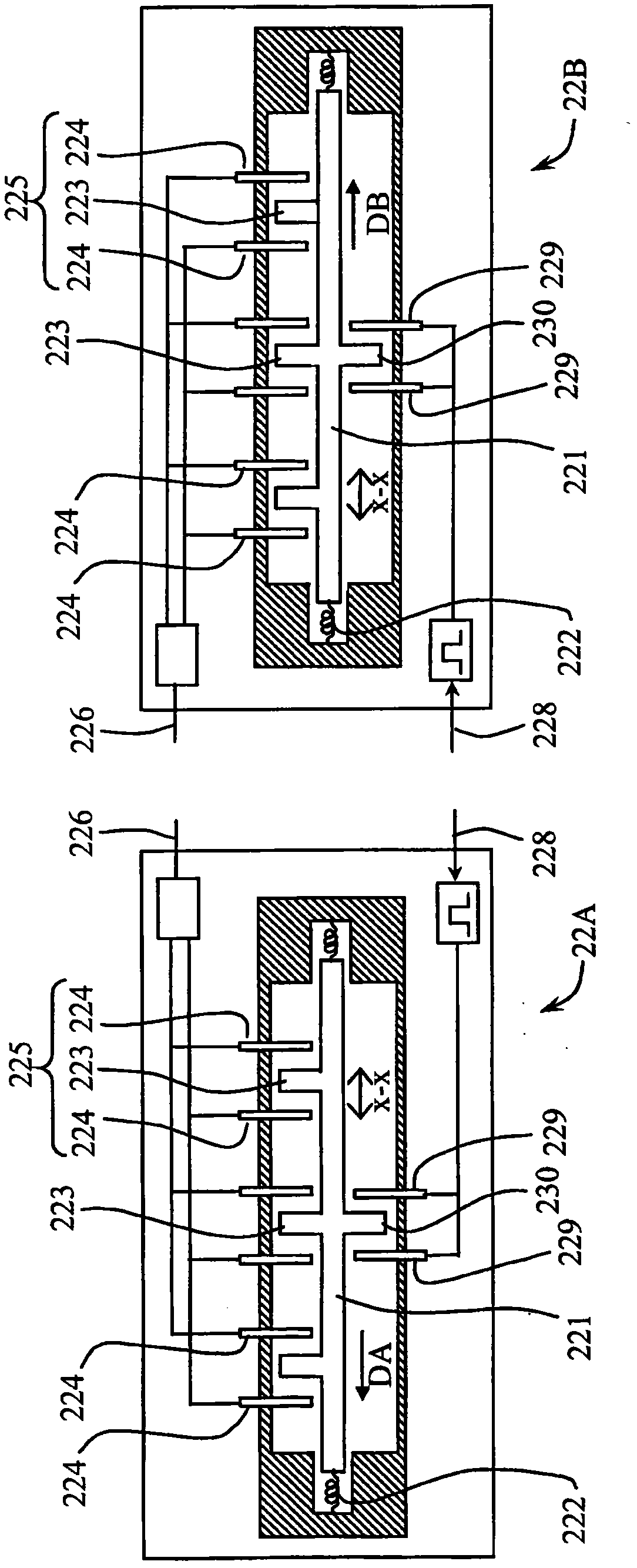
[0056] Such as figure 2 As shown, the two lateral acceleration sensors 22A, 22B are preferably of the MEMS (Micro Electro Mechanical Systems) type. Accelerometers of this type are well known in the art (see, for example, the SCA 1000 from VTI Technologies). The accelerometers 22A, 22B comprise inertial bodies in the form of polysi...


PUM


Abstract

A distributed safety monitoring system is provided with a first safety loop for connecting safety relays in series to a common power supply. The opening of any one of the safety relays can be detected by a current detector located in the safety loop. Each safety relay is part of a local safety monitoring device, which is provided with a local power supply and a test circuit, to allow local testing of the safety relay independently from the common power supply. Hence, the safety relays can be tested simultaneously.

Description

technical field [0001] The present invention relates to distributed safety systems, and more particularly to safety systems provided with safety loops for connecting distributed safety devices, such as vibration monitoring devices in railway vehicles. The invention also relates to a safety monitoring device for use in such a safety circuit, and to a method of testing such a system. Background technique [0002] Vibration monitoring systems for railway vehicles are known from the documents DE 100 20 519 , DE 100 20 520 and DE 100 20 521 . One or more accelerometers, preferably three-axis accelerometers, are connected to a central signal processing unit located at a remote location of the train consist. While this type of configuration may prove suitable for monitoring specific vehicle subsystems such as brakes, bogies or bodywork for diagnostic purposes, it does not provide the level of safety and reliability required for safety components. In particular, the transmission o...

Claims


Application Information

Patent Timeline
IPC IPC(8): G01R31/327G01R31/28B61L15/00H01H47/00
CPCG01R31/2827B61L15/0081H01H47/002B61L15/0036G01R31/3278B61L25/04G01R31/327G01R31/28H01H47/00
Inventor 迈克·贝尔特
Owner BOMBARDIER TRANSPORTATION GMBH
Learn More