Radiating module with heat conducting pipe and buckling type radiating fin in close fit with each other

A technology of heat dissipation fins and heat dissipation modules, which is applied in the direction of tubular components, heat exchange equipment, lighting and heating equipment, etc., can solve the problems of lack of mass production, low production efficiency, assembly errors, etc., to save manpower and assembly. The effect of cost, production capacity improvement and structural stability

Inactive Publication Date: 2011-08-10
LEMTECH PRECISION MATERIAL (CHINA) CO LTD
View PDF6 Cites 1 Cited by
  • Summary
  • Abstract
  • Description
  • Claims
  • Application Information

AI Technical Summary

Problems solved by technology

[0003] The traditional heat dissipation module mainly has the following two molding methods: 1. The heat dissipation fin assembly and the heat pipe are bonded together under high temperature conditions through a heat transfer medium. At the same time, the heat dissipation fin assembly needs to be post-treated with nickel. The cost is too high, the process is too many, and the heat conduction medium is mostly chemical substances, which will cause pollution in the process of nickelization; 2. Through the punching machine and the fixing fixture, the corresponding mechanism is designed outside the heat dissipation module production mold, and the heat conduction tube and the single fin The production efficiency is low, and assembly errors are prone to occur in this way, which is not suitable for mass production.

Method used


Image

  • Radiating module with heat conducting pipe and buckling type radiating fin in close fit with each other
  • Radiating module with heat conducting pipe and buckling type radiating fin in close fit with each other
  • Radiating module with heat conducting pipe and buckling type radiating fin in close fit with each other

Examples


specific Embodiment approach

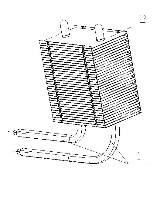
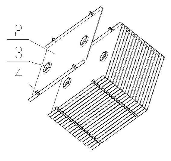
[0029] figure 1 It is a schematic diagram of a three-dimensional structure of an embodiment of the present invention; figure 2 It is the snap-fit ​​heat dissipation fin assembly described in the present invention.

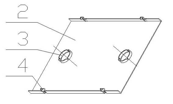
[0030] like figure 1 and figure 2 As shown: the heat pipe and snap-fit ​​heat dissipation fin tight-fit heat dissipation module includes a heat dissipation fin assembly and a heat pipe 1, wherein the heat dissipation fin assembly is formed by stacking a plurality of single fins 2, and each single fin 2 The two sides are bent upwards to form a bent edge of equal height, and the body of each single fin 2 is provided with a fin turning hole 3 turned out toward the bending direction of the bent edge. There are at least two fin turning holes 3, and the number of heat pipes 1 is the same as the number of fin turning holes 3. In this embodiment, there are two fin turning holes 3 on a single fin 2, The number of heat pipes 1 is the same as the number of fin turning h...


PUM


Abstract

The invention discloses a radiating module with a heat conducting pipe and a buckling type radiating fin in close fit with each other. The radiating module comprises a radiating fin component and the heat conducting pipe, wherein the radiating fin component is formed by laminating a plurality of pieces of single fins; two sides of each piece of the single fin are bent upwards to form bend sides with equal height, while the body of the each piece of the single fin is provided with a fin turning hole turned over towards a bending direction of the bend side, wherein the fin turning hole is lower than the bend side; and except for the uppermost single fin, bend sides on two sides of other single fins are provided with a buckling point respectively; the single fins are connected with each other via the buckling points, and are laminated together to form the radiating fin component; and the heat conducting pipe passes through the fin turning hole of each single fin to be fixedly connected with the radiating fin component. The radiating module is simple in structure, few in production processes and environment-friendly; moreover, the working efficiency is greatly improved, the accidents of putting less fins than supposed to or missing the fins when laminating the fins are effectively prevented, and the quality and the performance of a product are guaranteed.

Description

technical field [0001] The invention relates to a heat dissipation module, in particular to a closely fitted heat dissipation module with a heat conduction pipe and snap-fit ​​heat dissipation fins, which belongs to the technical field of heat dissipation devices. Background technique [0002] Existing heat dissipation modules include heat dissipation fin components and heat pipes. The heat source dissipates heat, so that multiple heat dissipation fins form a large-area heat dissipation combination. [0003] The traditional heat dissipation module mainly has the following two molding methods: 1. The heat dissipation fin assembly and the heat pipe are bonded together under high temperature conditions through a heat transfer medium. At the same time, the heat dissipation fin assembly needs to be post-treated with nickel. The cost is too high, the process is too many, and the heat conduction medium is mostly chemical substances, which will cause pollution in the process of nic...

Claims


Application Information

Patent Timeline
Patent Type & Authority Applications(China)
IPC IPC(8): F28F1/30B21D53/08
Inventor 盛敏飞李配宇
Owner LEMTECH PRECISION MATERIAL (CHINA) CO LTD
Why Eureka
Try Eureka