DC power supply apparatus

A technology of DC power supply and rectifier circuit, which is applied to output power conversion devices, electrical components, and AC power input to DC power output, etc., and can solve the problems of high harmonic current component content, synchronous rectification, damage, etc. , to achieve the effect of reducing the high-order harmonic current, improving the power factor of the power supply, and high-order harmonic current being efficient.

Inactive Publication Date: 2011-08-10
MITSUBISHI ELECTRIC CORP
View PDF8 Cites 4 Cited by
  • Summary
  • Abstract
  • Description
  • Claims
  • Application Information

AI Technical Summary

Problems solved by technology

[0002] In the rectifier circuit of the conventional DC power supply unit, the input current input from the commercial power supply to the DC power supply unit cannot be rectified synchronously with the voltage of the commercial power supply, so the power factor of the power supply deteriorates and the amount of reactive power is large, that is, the power utilization rate deteriorates. such subjects
The amount of reactive power refers to the amount of supplied power returned to the supply side without being consumed by the load-side device connected via the DC power supply device. When viewed from the supply source, the efficiency of power generation and transmission deteriorates. Viewed from the side, it is in a state where the supplied power is not effectively utilized
In addition, in the conventional DC power supply device, the waveform of the input current input from the commercial power supply is distorted from the sinusoidal waveform, that is, there is a problem that the content of the high-order harmonic current component is large, and there is a problem that the same power supply is hindered. Issues such as operation of other devices connected to the system or damage to power transmission equipment

Method used


Image

  • DC power supply apparatus
  • DC power supply apparatus
  • DC power supply apparatus

Examples


Embodiment approach 1

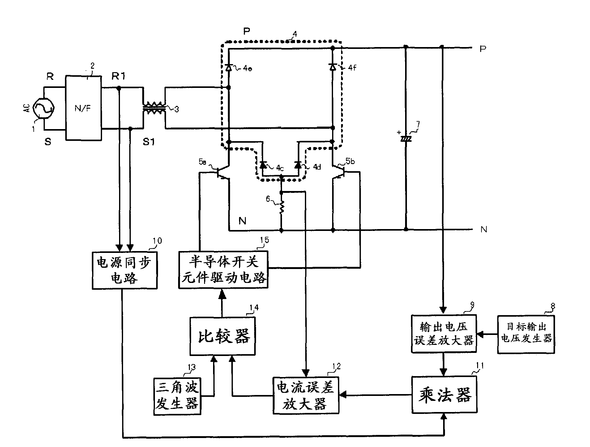
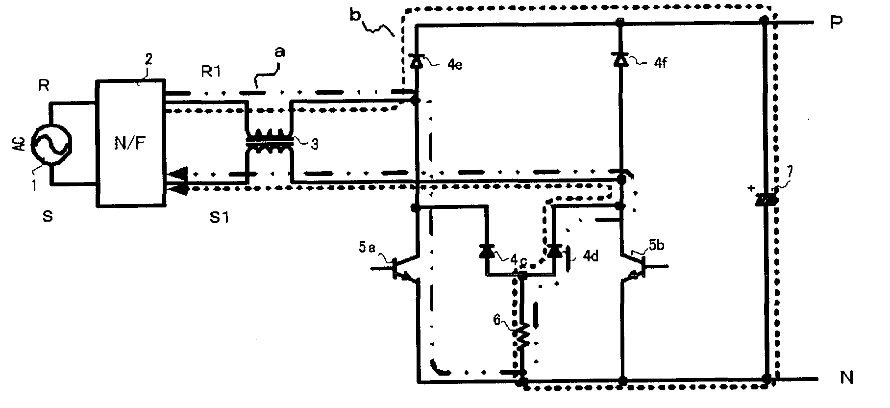
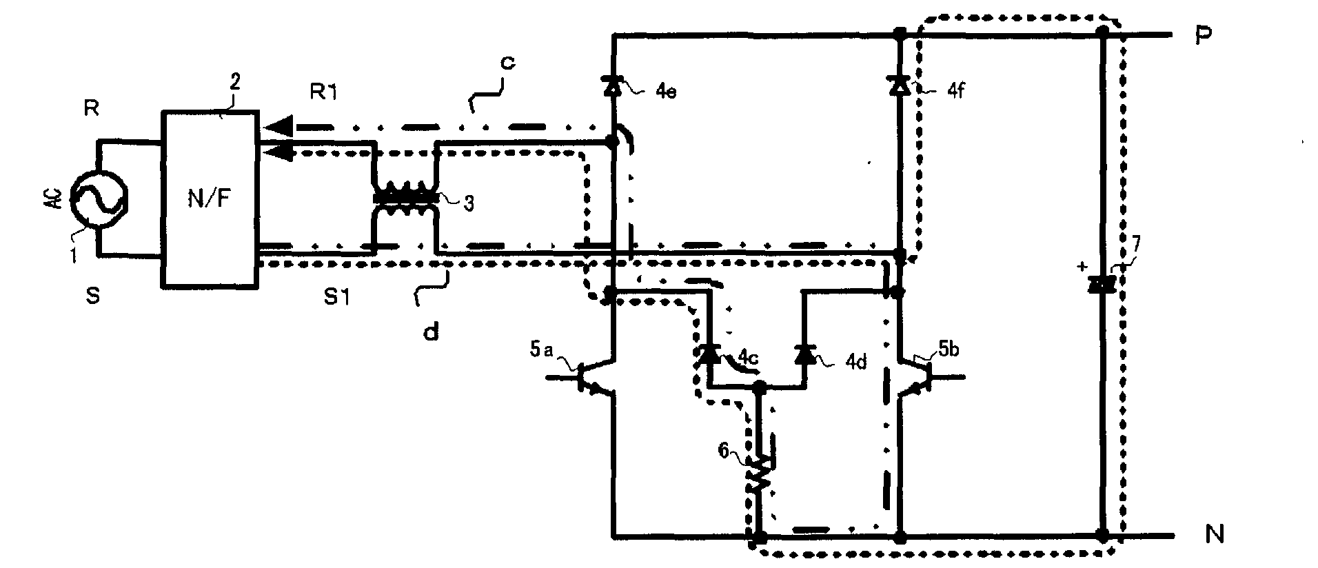
[0025] figure 1 It is a circuit configuration diagram of the half-bridge converter circuit in Embodiment 1 of the present invention, which is used in home appliances such as air conditioners to improve the power factor of the power supply, reduce the harmonic current of the power supply, and control the DC output voltage. Adjusted DC power supply unit. Hereinafter, this circuit will be described as an example. The AC power supply 1 is connected to a rectification circuit 4 via a noise filter 2 and a reactor 3 . The rectifier circuit 4, that is, the diode bridge circuit, is composed of rectifier elements, namely, diodes 4c, 4d, 4e, and 4f. The rectifier elements 4e, 4f are connected to the positive terminal side of the rectifier circuit 4, and the rectifier elements 4c, 4d are connected to the negative terminal side. The shunt resistor 6 for current detection is connected to the negative terminal. Also, semiconductor switching elements 5a, 5b that perform switching operation...


PUM


Abstract

The invention provides a DC power supply apparatus. In the case of applying an AC power supply voltage about 100V - 240V to a DC power supply apparatus connected with an industry power supply for the high-frequency switch, there is a problem that there is no high voltage resistance and high current resistance rectifying element which can track the high-speed switch action of an semiconductor switch element of a high-frequency switch. Further, when the switching frequency is increased in the constituent components of the related art, the loss of each of the semiconductor elements, that is, the rectifying elements and the semiconductor switch elements on a path for flowing the current from the DC power supply apparatus becomes large. Thus, there arise problems that the efficiency of the DC power supply apparatus reduces and the semiconductor elements can not withstand heat generated by the loss and are burnt. The rectifying element cooperatively operating with the switching action of the semiconductor switch element is a semiconductor element which is formed by using a Schottky junction formed between silicon carbide or gallium nitride and metal and has a withstanding voltage property with respect to a voltage of an AC power supply.

Description

technical field [0001] The invention relates to a DC power supply device for performing AC-DC conversion. Background technique [0002] In the rectifier circuit of the conventional DC power supply unit, the input current input from the commercial power supply to the DC power supply unit cannot be rectified synchronously with the voltage of the commercial power supply, so the power factor of the power supply deteriorates and the amount of reactive power is large, that is, the power utilization rate deteriorates. Such subjects. The amount of reactive power refers to the amount of supplied power returned to the supply side without being consumed by the load-side device connected via the DC power supply device. When viewed from the supply source, the efficiency of power generation and transmission deteriorates. Viewed from the side, the supplied electric power is not effectively utilized. In addition, in the conventional DC power supply device, the waveform of the input curren...

Claims


Application Information

Patent Timeline
Patent Type & Authority Applications(China)
IPC IPC(8): H02M7/12H02M1/42H02M1/12
CPCH02M7/219Y02B70/1483Y02B70/10
Inventor 天野胜之铃木大介斋藤胜彦
Owner MITSUBISHI ELECTRIC CORP
Why Eureka
Try Eureka