
Constant-current driving electronic transformer

An electronic transformer, constant current drive technology, applied in the field of electronic transformers, can solve the problems of no protection function, short-term, electronic transformer and lamp damage, etc., to achieve the effect of simple circuit, constant output current, and increased lamp life

Inactive Publication Date: 2011-08-10
SHANGHAI RONGJI CONTROL SYST
View PDF1 Cites 3 Cited by
  • Summary
  • Abstract
  • Description
  • Claims
  • Application Information

AI Technical Summary

Problems solved by technology

[0005] 3. LED lights using traditional electronic transformers are easy to flicker
[0006] 4. LED life, the life of LED lamps using traditional electronic transformers is generally 20KHr, which is relatively short
[0007] 5. The traditional electronic transformer has no overvoltage protection. When the output voltage is too high, there is no protection circuit, which will cause damage to the electronic transformer and lamps.
[0008] 6. The traditional electronic transformer has no protection function when the output is short-circuited
[0009] 7. If the traditional electronic transformer is heated again, it will not protect the function until it is damaged
[0010] 8. The efficiency of traditional electronic transformers is low, generally less than 70%

Method used


Image

  • Constant-current driving electronic transformer
  • Constant-current driving electronic transformer
  • Constant-current driving electronic transformer

Examples


Embodiment Construction

[0026] In order to make the technical means, creative features, goals and effects achieved by the present invention easy to understand, the present invention will be further described below in conjunction with specific embodiments.

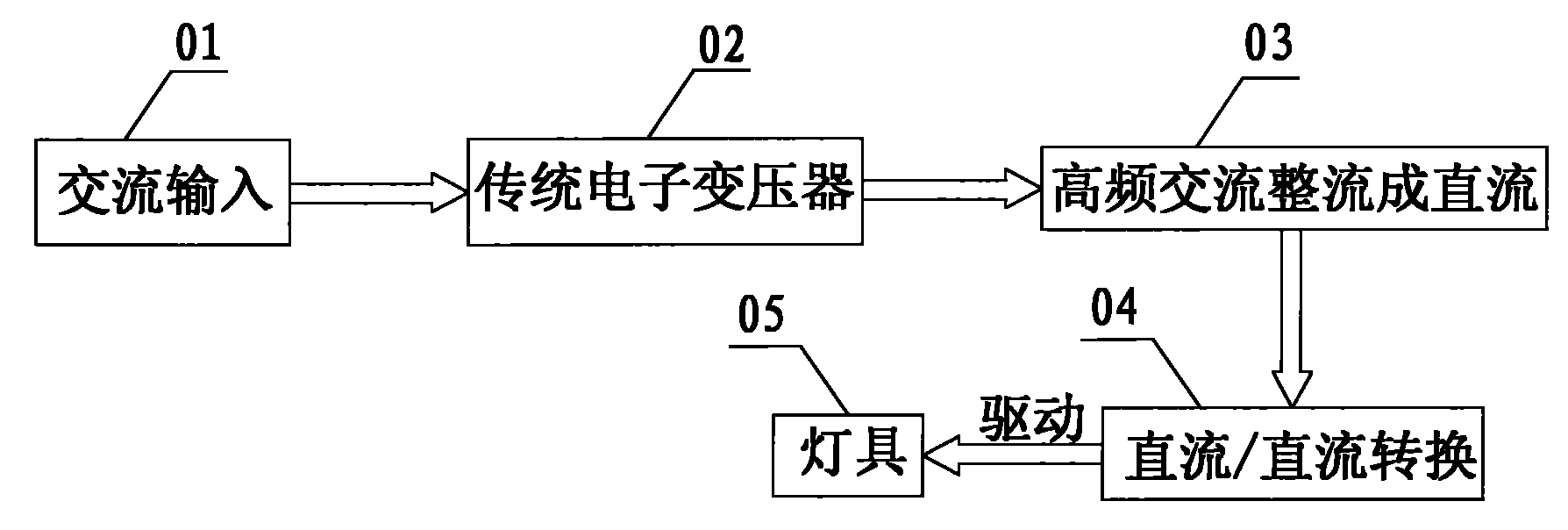
[0027] see figure 1 , the scheme of traditional electronic transformer driving lamps is: firstly, the AC input 01, 220V AC enters the traditional electronic transformer 02, and then the high-frequency AC is rectified into DC 03 through the transformer, and then the DC / DC conversion 04 process is carried out. This process consists of The DC / DC conversion chip completes the DC conversion, and finally drives the lamp 05. The whole process is realized in two stages. First, the power frequency AC is converted into high frequency AC, and then converted into DC. The circuit is complex; the output voltage is easy to change, the current is unstable, and the lamps are easy to flicker, and there is no overvoltage and overheating protection circuit in the tra...


PUM


Abstract

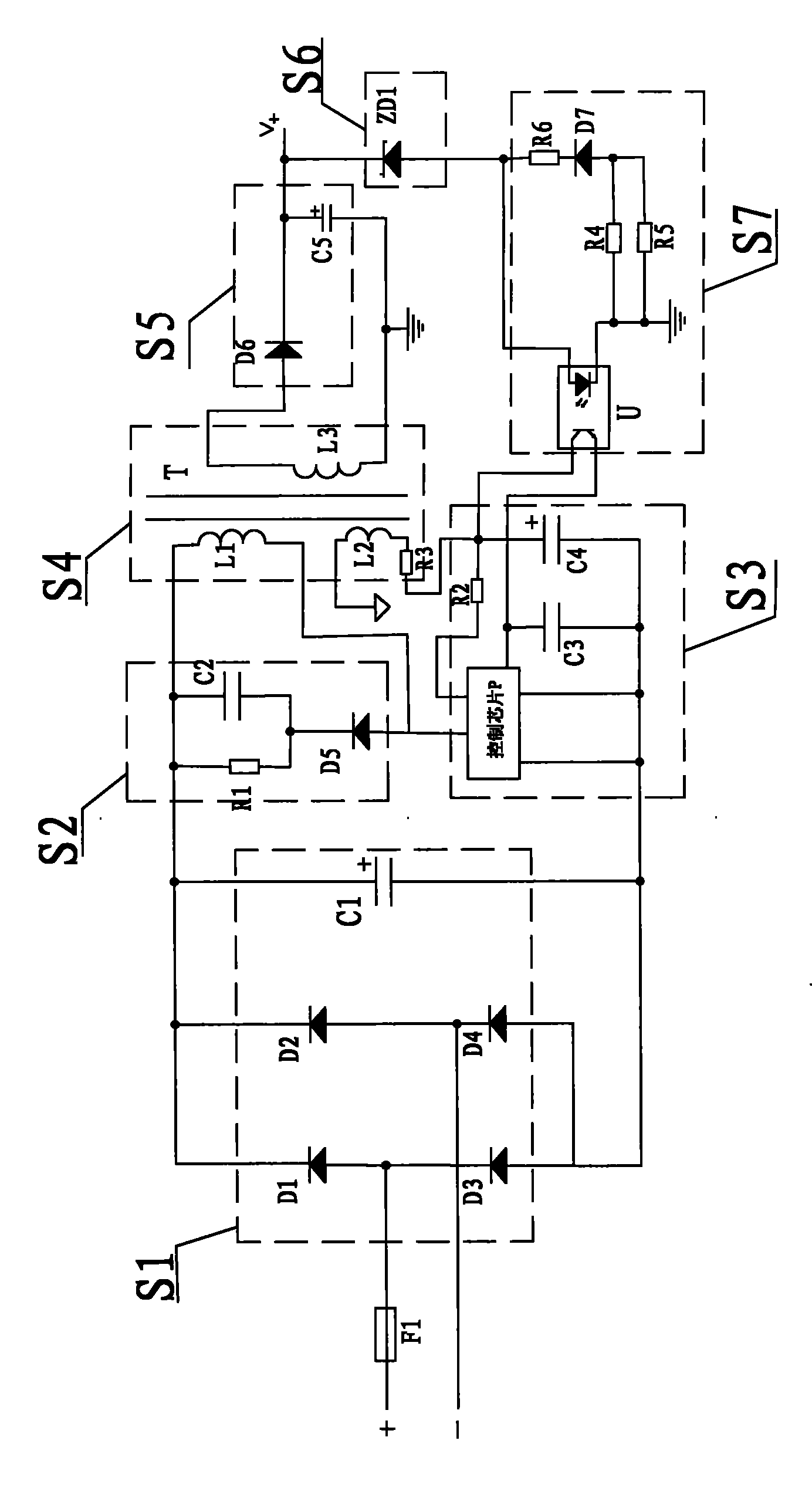
The invention discloses a constant-current driving electronic transformer, which is arranged outside a lamp. The electronic transformer is connected to the outer side of the lamp and connected with a high-frequency switch and a control circuit and a voltage-converting circuit through an alternating current / direct current rectifying circuit at the same time. The voltage-converting circuit is connected with an output rectifying circuit. The alternating current / direct current rectifying circuit consists of a bridge-type rectifying circuit which is formed by connecting four diodes, and a parallelly-connected high-voltage electrolytic capacitor. The output rectifying circuit rectifies the current into a direct-current output voltage for driving the connected lamp in the constant-current driving mode. The high-frequency switch and the control circuit are connected with an output constant-current control circuit. An output overvoltage protection circuit consisting of voltage-stabilizing diodes is arranged between the output rectifying circuit and the output constant-current control circuit. In the constant-current driving electronic transformer, conversion between alternating current and direct current is realized and the circuit is relatively simple, the constant-current driving electronic transformer is connected outside the lamp, directly drives the lamp by the constant current, is constant in output current, causes no glint of the lamp and has the functions of short-circuit protein and overheating protection.

Description

technical field [0001] The invention relates to the field of electronic transformers, in particular to a constant current driven electronic transformer. Background technique [0002] With the development of society and the advancement of science and technology, electronic transformers have gradually entered the market, and various low-power (3W-30W) energy-saving lamp products are widely used in electronic transformers. The development and promotion of foreign countries in this area is better. According to relevant information, in some countries such as the United States and Japan, the state formulates relevant policies to actively encourage and promote the use of electronic transformers, and continuously improves the performance of electronic transformers, which greatly promotes the development of electronic transformers. And popularize the green lighting project of electronic transformers. With the rapid development of domestic economic construction and the implementation...

Claims


Application Information

Patent Timeline
Patent Type & Authority Applications(China)
IPC IPC(8): H05B37/02H02M7/08
Inventor 俞展
Owner SHANGHAI RONGJI CONTROL SYST
Learn More