
Method for tightly fitting heat pipe with heat sink

A heat sink and heat pipe technology, applied in the field of its tight connection, can solve problems such as gaps, low production capacity, and loss of adhesion effect

Inactive Publication Date: 2011-08-10
陈世明
View PDF8 Cites 2 Cited by
  • Summary
  • Abstract
  • Description
  • Claims
  • Application Information

AI Technical Summary

Problems solved by technology

[0004] In addition, there are also operators who apply heat-conducting adhesive between the heat-dissipating pipe and the heat-dissipating body, and use gluing processing technology to combine the heat pipe and the heat-dissipating body. Polymer materials will lose their adhesive effect due to time curing or deterioration, resulting in gaps and affecting heat conduction performance. Therefore, it is necessary to improve the above shortcomings

Method used


Image

  • Method for tightly fitting heat pipe with heat sink
  • Method for tightly fitting heat pipe with heat sink
  • Method for tightly fitting heat pipe with heat sink

Examples


no. 1 example

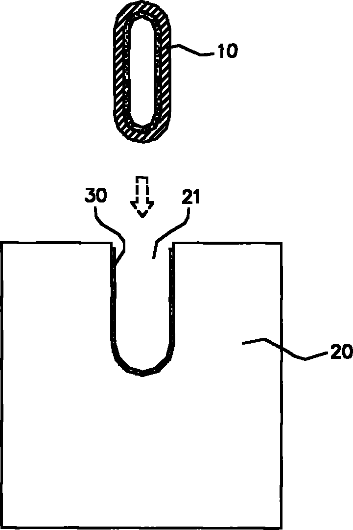
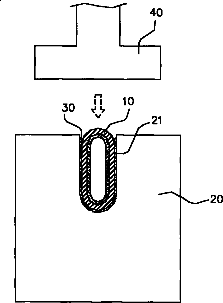
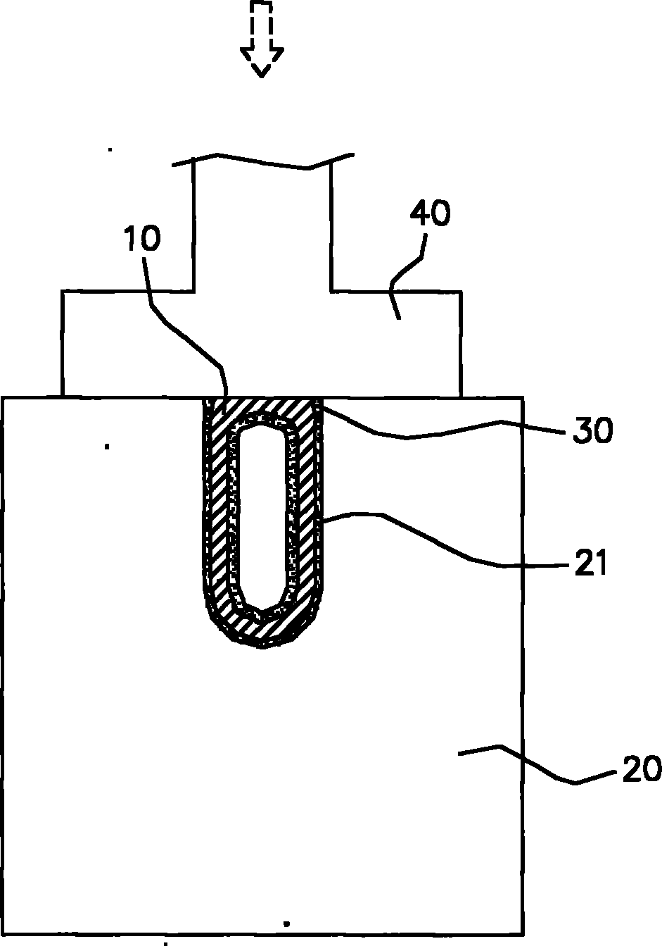
[0027] See first Figure 1A -D is the first embodiment of the present invention, which is a method for tightly fitting a heat pipe and a radiator, comprising the following steps:

[0028] a), provide at least one heat pipe 10, the heat pipe 10 is slightly shoulder-shaped or oblong, and slightly protrudes from the surface of the radiator 20, and a radiator 20 for conducting heat with the heat pipe 10, the radiator 20 is Any one of the heat conduction plate, the heat conduction base or the fin module, and a U-shaped groove 21 for accommodating the heat pipe 10 is provided on one side of the radiator 20;

[0029] b), placing the heat pipe 10 in the groove 21, and coating the heat-conducting medium 30 on its joint surface, and preparing a stamper 40; c), pressing the stamper 40 corresponding to the heat pipe 10 in the groove 21, One end of the heat pipe 10 is stamped and applied by the die 40, causing the heat pipe 10 to be deformed, and then pressed and tightly integrated with th...

no. 3 example

[0033] continued see Figure 3A -E, is the third embodiment of the present invention, a method for tightly fitting a heat pipe and a radiator, comprising the following steps:

[0034] a), provide at least one heat pipe 50, the heat pipe 50 is slightly oblate or oblong, and a radiator 60 for conducting heat with the heat pipe 50, the radiator 60 includes a plurality of fins 61, and on these The fin 61 is provided with a through hole 62 for providing and accommodating the heat pipe 50;

[0035] b), insert the heat pipe 50 into the aforementioned through hole 62, and coat the heat-conducting medium 70 on its combined joint surface, position the heat pipe 50 section between the two fins 61 on the jig 80, and prepare a die 82;

[0036] c) Punch the die 82 corresponding to the jig 80 to stamp the heat pipe section between the two fins 61, the heat pipe section located at both ends of the fin 61 is pressed by the die 82 and bulges toward the through hole 62 of the fin 61 deformatio...


PUM


Abstract

The invention discloses a method for tightly fitting a heat pipe with a heat sink, comprising the following steps: a) providing at least one heat pipe and a heat sink for conducting heat with the heat pipe, wherein the heat sink is a heat conduction plate or a fin group and is provided with a groove or a through hole for assembling and containing the heat pipe; b) putting the heat pipe into the groove or the through hole, and preparing a pressing die; c) causing the pressing die to correspond to the heat pipe in a stamping groove or a heat pipe section between two fins, stamping and applying force on one end of the heat pipe or the heat pipe section to accelerate the peripheral wall of the heat pipe to deform or hunch to the through hole for deformation; and pressing the peripheral wall with the groove or the through hole to be combined into a whole. According to the above characteristics, quick and effective combination efficiency is provided, and the heat pipe and the heat sink are tightly combined to satisfy the requirement of the heat source on high-efficiency heat dissipation.

Description

technical field [0001] The invention relates to a method for tight fitting of a heat pipe and a heat sink, especially to the technical field of heat dissipation for devices such as computers, electronics or diode lamps or industries thereof, and a tight connection method thereof. Background technique [0002] In order to provide better heat dissipation performance of heat sinks such as computers, electronics or diode lamps, heat sinks must cooperate with heat pipes. Generally, heat sinks are commonly used as heat sinks (or heat sink bases) or fin modules. The heat source is thermally bonded, and the heat conduction is quickly removed through the heat pipe to meet the heat dissipation requirements of the heat source. [0003] The known method of fastening the heat pipe and the radiator is to use solder to weld the joint surface of the heat pipe and the fins, but this welding method is not only environmentally friendly but also extremely cumbersome, not only must apply solder ...

Claims


Application Information

Patent Timeline
Patent Type & Authority Applications(China)
IPC IPC(8): H05K7/20
Inventor 陈世明
Owner 陈世明
Learn More