
Air conditioner

A technology for air conditioners and humid air, which is applied in air conditioning systems, refrigerators, compressors, etc., to reduce the reduction of deodorization effect, maintain deodorization effect, and improve deodorization effect.

Inactive Publication Date: 2011-08-10
DAIKIN IND LTD
View PDF7 Cites 2 Cited by
  • Summary
  • Abstract
  • Description
  • Claims
  • Application Information

AI Technical Summary

Problems solved by technology

Heat exchange between indoor heat exchanger and indoor air

Method used


Image

  • Air conditioner
  • Air conditioner
  • Air conditioner

Examples


Embodiment Construction

[0045]

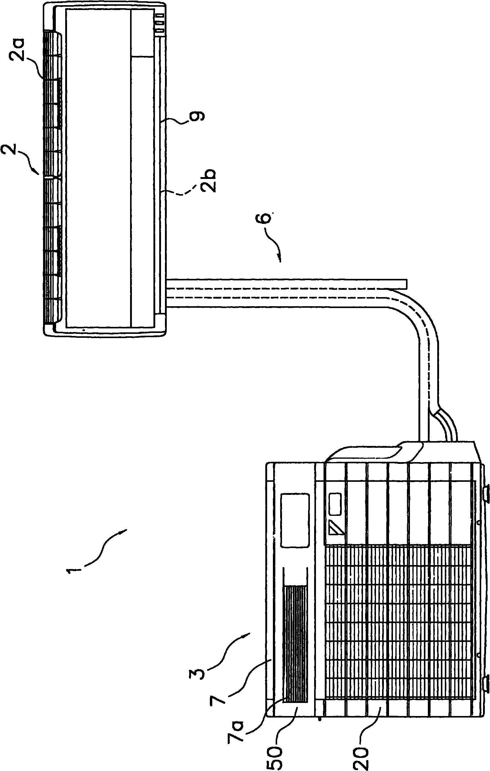
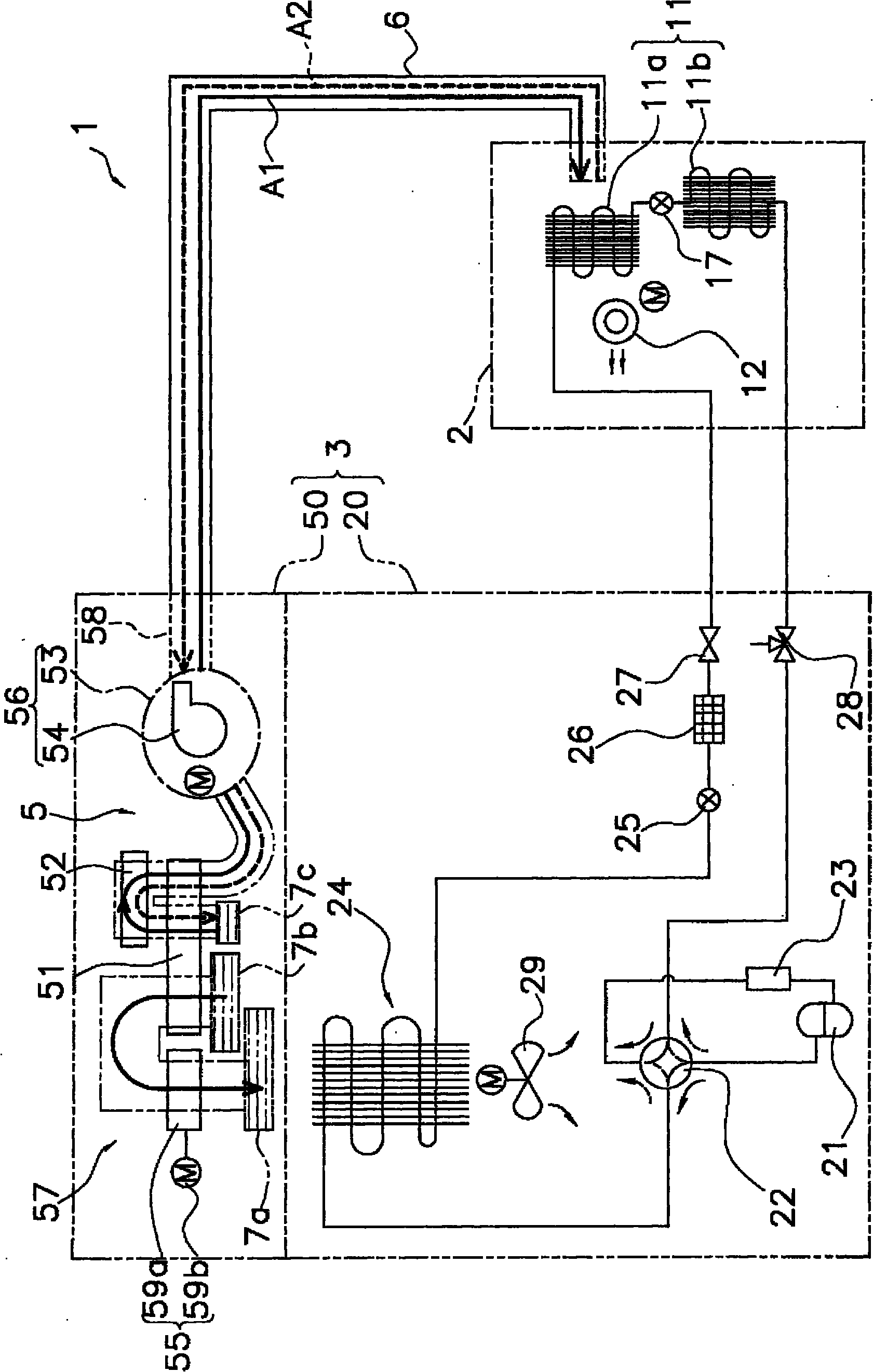
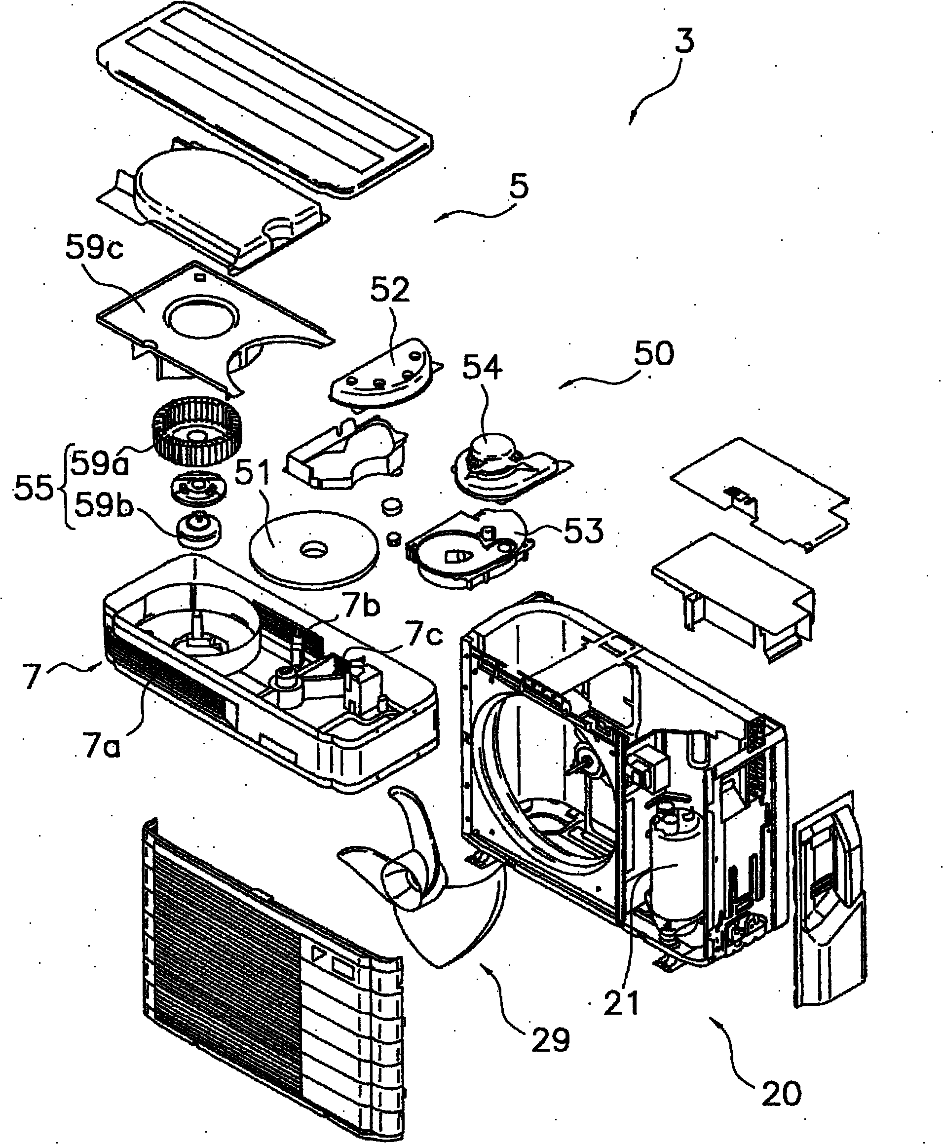
[0046] like figure 1 and figure 2As shown, an air conditioner 1 according to one embodiment of the present invention has an outdoor unit 3 and an indoor unit 2 . In addition, this air conditioner 1 can perform a deodorizing operation for deodorizing a room in addition to normal operations such as cooling operation, heating operation, humidification operation, air supply operation, and exhaust operation. In addition, the deodorizing operation referred to here refers to an operation capable of emitting into the air odorous components, etc. that have permeated indoor fabrics, building materials, etc., and discharging the odorous components that have diffused into the air to the outside. In addition, the outdoor unit 3 has an outdoor air-conditioning unit 20 and a humidification unit 50, and the outdoor air-conditioning unit 20 houses an outdoor heat exchanger 24, an outdoor fan 29, and the like inside. An indoor heat exchanger 11 is accommodated inside the indoor un...


PUM


Abstract

Disclosed is an air conditioner (1) equipped with a room heat exchanger (11), a humidification unit (50), and a control unit (60). The room heat exchanger (11) exchanges heat with the air in a room. The humidification unit (50) is capable of supplying very humid air having higher moisture content than that of the room air to the room. The control unit (60) performs a deodorizing operation that includes a water-filter phase wherein a dehumidifying operation and an air supply operation are performed simultaneously. In the dehumidifying operation, the room air is dehumidified by at least a second room heat exchanger (11b) of the room heat exchanger (11). Furthermore, in the air supply operation, very humid air is supplied to the room by means of the humidification unit (50).

Description

technical field [0001] The present invention relates to an air conditioner with humidification function and dehumidification function. Background technique [0002] Conventionally, there has been proposed a method of condensing air whose relative humidity has been increased by humidification or the like, thereby recovering odorous components contained in the air together with condensed water. [0003] For example, the air cleaner disclosed in Patent Document 1 (JP-A-2005-106358) includes a humidifier that humidifies air taken in from the room, and a dehumidifier that dehumidifies the air humidified by the humidifier. In this air cleaner, the humidity of polluted air taken in from the room is raised in the humidifier to generate high-humidity air, and the generated high-humidity air is dehumidified in the dehumidifier. At this time, the dehumidified air is purified by taking in pollutants in the air into the condensed water condensed by dehumidification. Thus, this air clea...

Claims


Application Information

Patent Timeline
Patent Type & Authority Applications(China)
IPC IPC(8): F24F1/00F24F11/02F24F6/00F24F8/10F24F8/117
CPCF24F6/00F25B2313/005F24F2003/1617F24F3/14F24F11/0008F24F3/153F24F3/1603F24F2003/1446Y02A50/20F24F8/117F24F8/10
Inventor 松原笃志
Owner DAIKIN IND LTD
Learn More