
Direct power control with component separation

A controller and power output technology, applied in vector control systems, control systems, control generators, etc., can solve problems such as wear and high mechanical components

Active Publication Date: 2011-08-10
SEG SCHALTANLAGEN ELEKTRONIK GERATE
View PDF4 Cites 7 Cited by
  • Summary
  • Abstract
  • Description
  • Claims
  • Application Information

AI Technical Summary

Problems solved by technology

However, conventional control methods are not optimized to deal with unbalanced grid voltages because unbalanced grid voltages cause unbalanced stator currents that generate torque ripple of the rotor
This results in higher wear on mechanical elements (e.g. wind turbines)

Method used


Image

  • Direct power control with component separation
  • Direct power control with component separation
  • Direct power control with component separation

Examples


Embodiment Construction

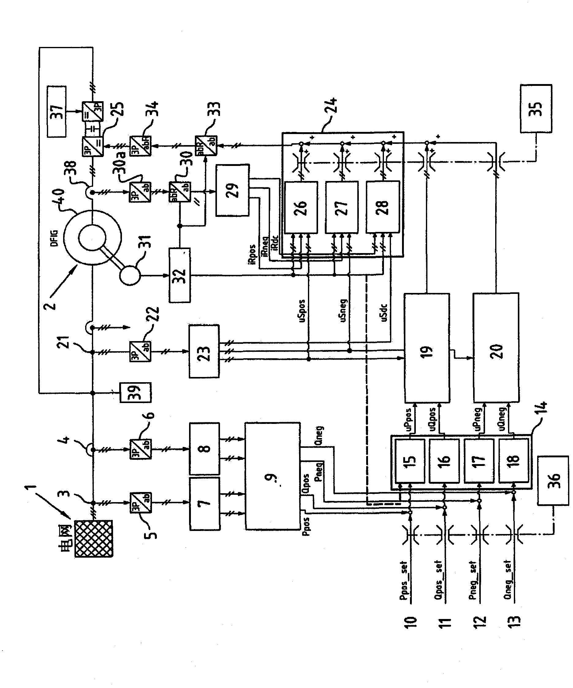
[0028] first, figure 1 A utility grid 1 and a doubly-fed induction machine 2 abbreviated DFIG are shown. In order to provide the method of the invention, means are shown for measuring the grid voltage 3 and the grid current 4, both in a three-phase system. Thereafter, the measured grid voltage and grid current are transformed into the stator frame coordinate system ab by means of the means 5 , 6 . Derived from the stator frame coordinate system, the positive and negative sequence systems are defined and the measured voltage and current values ​​are transformed into these two systems.

[0029] Typically, the voltage and current vectors in a positive sequence system circulate at 50 Hz, 60 Hz respectively in the mathematical forward direction, while these vectors in a negative sequence system also circulate at 50 Hz, 60 Hz respectively in the opposite direction. In blocks 7 , 8 the components of the positive-sequence and negative-sequence systems of the measured grid voltage 3 an...


PUM


Abstract

The invention relates to a method to control power output of a doubly-fed induction machine to a grid including the steps of measuring grid voltage and grid current in a three phase coordinate system, transforming grid voltage and grid current into a stator frame coordinate system, decomposing the grid voltage and grid current in the stator frame coordinate system in a positive sequence system and in a negative sequence system, calculating active and reactive power in the positive and negative sequence system, and controlling active and reactive power in the positive and negative sequence system.; The object to provide a method to control power output of a doubly-fed induction machine which provides good dynamics and is able to allow fault-ride-through operations when unbalanced grid voltages occurs is solved in that active and reactive power in the positive and negative sequence system are used as independent state variables in a state controller, whereas the state controller generates manipulated values in the positive and negative sequence system separately which are subjected as manipulated state vectors to a state feedback in a stator frame coordinate system without further control loops before the manipulated vector resulting from state feedback is used to set the rotor voltage.

Description

technical field [0001] The invention relates to a method for controlling the power output of a doubly-fed induction motor to a power grid, comprising the steps of: [0002] - Measurement of grid voltage and grid current in a three-phase coordinate system; [0003] - Transform the grid voltage and grid current into the coordinate system of the stator frame; [0004] -Decompose the grid voltage and grid current in the stator frame coordinate system into positive sequence system and negative sequence system; [0005] - Calculation of active and reactive power in positive and negative sequence systems; and [0006] - Control of active and reactive power in positive and negative sequence systems. [0007] Furthermore, the invention relates to a device for controlling the power output of a doubly-fed induction machine (DFIG) to the grid, a computer program enabling processor means to control the power output of a doubly-fed induction machine, and an advantage to the inventive met...

Claims


Application Information

Patent Timeline
Patent Type & Authority Applications(China)
IPC IPC(8): H02P9/00
CPCH02J3/382Y02E40/50Y02E10/763H02P2009/004H02P9/007H02J3/26H02J3/386H02P2101/15H02P21/00H02J2300/28H02J3/381Y02E10/76H02J3/48H02J3/50
Inventor 斯特凡·恩格尔哈特约尔格·克雷奇曼
Owner SEG SCHALTANLAGEN ELEKTRONIK GERATE
Learn More