Orthodontic force measuring device

A measuring device and orthodontic technology, which is applied in dentistry, medical science, etc., can solve the problems of reducing the effect of orthodontic treatment, delaying treatment time, and difficult internal measurement, so as to shorten the time of orthodontic treatment, improve the treatment effect, and broaden the development prospects Effect

Inactive Publication Date: 2011-08-17
SOUTHEAST UNIV
View PDF6 Cites 12 Cited by
  • Summary
  • Abstract
  • Description
  • Claims
  • Application Information

AI Technical Summary

Problems solved by technology

[0002] In clinical orthodontic treatment, the orthodontic force is generated by the elastic deformation of the appliance. Excessive orthodontic force applied to the teeth will cause root absorption, tooth bleeding, and even lead to negative effects such as root necrosis. Too small orthodontic force will reduce the tooth quality. Correction effect and delayed treatment time bring a lot of inconvenience to patients. Therefore, appropriate orthodontic force has an important impact on orthodontic treatment, and the measurement of orthodontic force is particularly necessary
[0003] At present, the domestic measurement devices for orthodontic force measurement are carried out in vitro, and the orthodontic force is measured indirectly with the help of measuring tools such as calipers, and the measurement accuracy is low. In vitro measurement often requires the plaster model of the tooth and jaw, and the measurement cost is high. Long cycle and inconvenient operation
Foreign countries have introduced that the stress sensor is integrated in the sensitive bracket, and the orthodontic force is calculated by measuring the stress, but it is only used for in vitro experimental measurement. The measurement process requires the use of computer equipment for data processing and conversion. The measurement process is complicated and difficult. for in vivo measurements

Method used


Image

  • Orthodontic force measuring device
  • Orthodontic force measuring device
  • Orthodontic force measuring device

Examples


Embodiment Construction

[0024] The present invention will be further described below in conjunction with the accompanying drawings of the description.

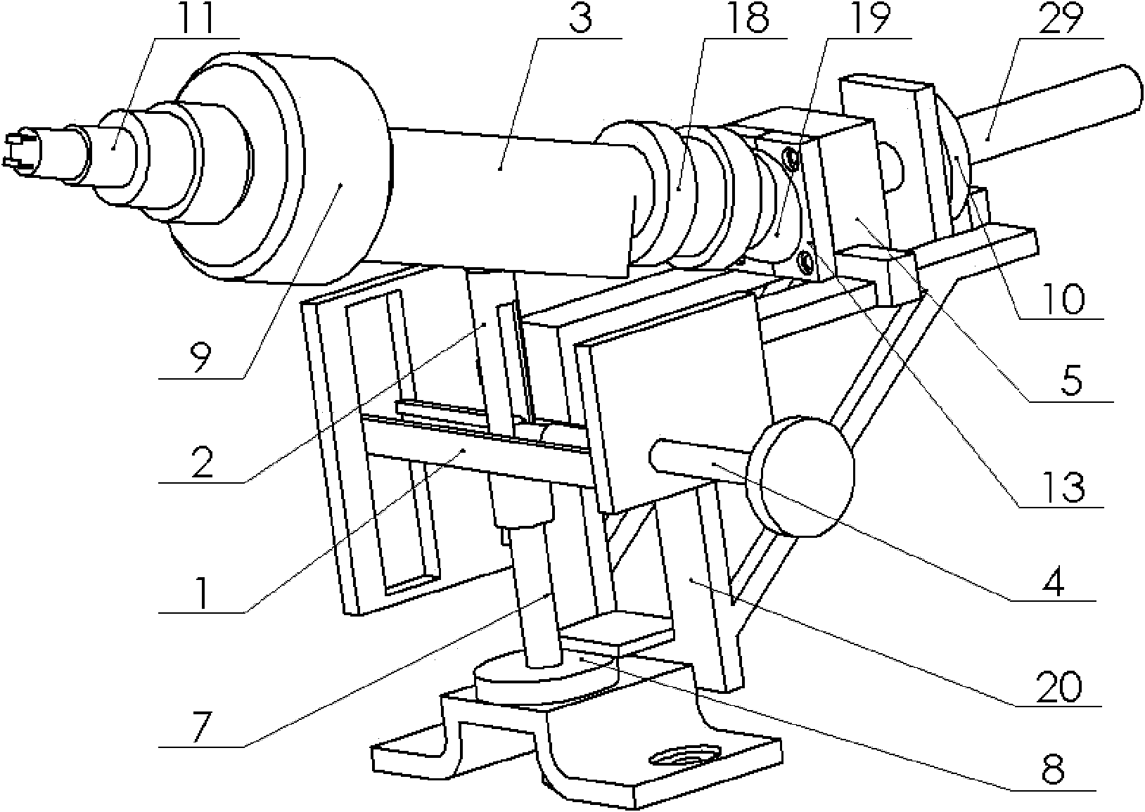
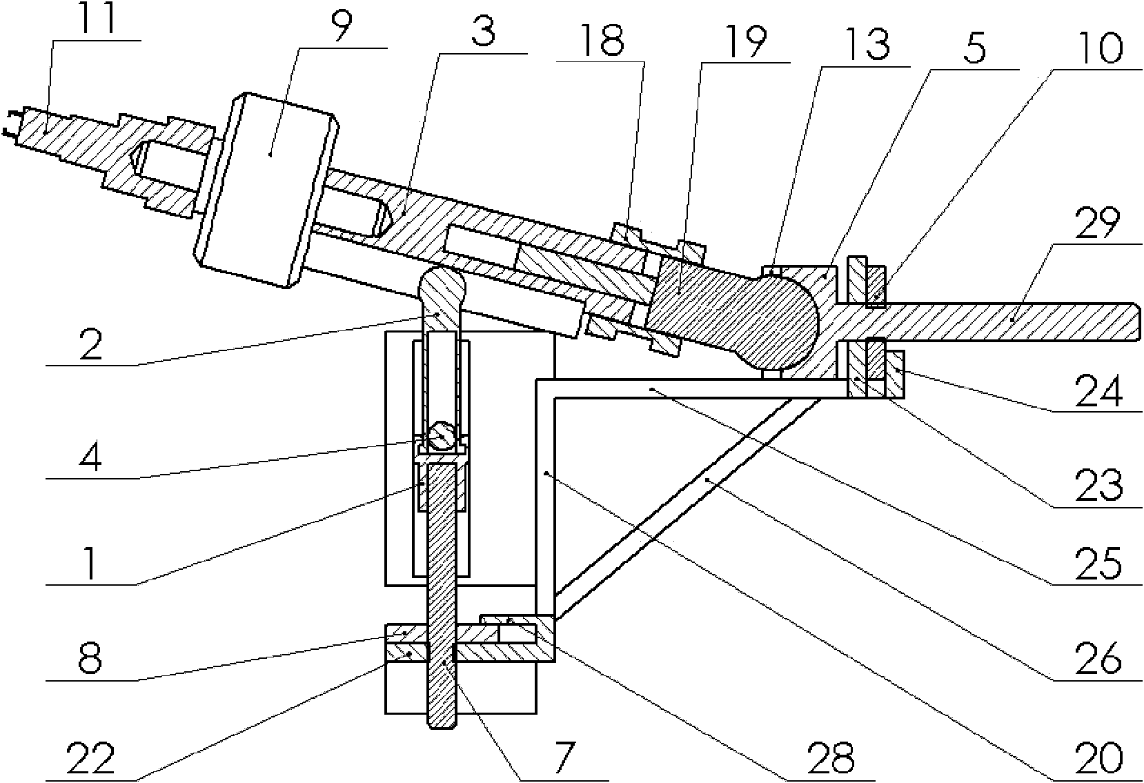
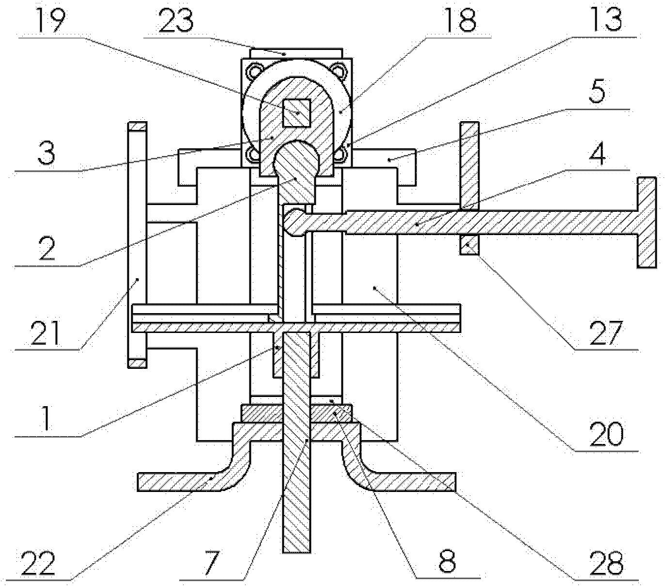
[0025] The orthodontic force measuring device for orthodontics of the present invention includes a base, an adjustment module and a measurement module; the base includes a vertical riser 20, and the lower part of the riser 20 is connected with a base 22 and a lower stopper 28, The base 22 is in the shape of a "several" and includes a horizontal upper end surface and ear surfaces on both sides of the upper end surface. The upper end surface is provided with round holes, and the two ear surfaces are provided with round holes. A bayonet is formed between the upper end surfaces of the vertical plate 20; the two sides of the vertical plate 20 are respectively connected with a square groove baffle plate 21 with a vertical square groove and a screw hole baffle plate 27 with a screw hole; the upper end of the vertical plate 20 is connected with a horizontally...


PUM


Abstract

The invention relates to an orthodontic force measuring device which comprises a base, an adjusting module and a measuring module, wherein the base is connected with the adjusting module used for adjusting the measuring module in a three-dimensional way; the base is connected with the measuring module by the adjusting module; the measuring module comprises a center rod, a pull pressure sensor and a clamp head; one end of the pull pressure sensor is connected with the center rod, and the other end of the pull pressure sensor is connected with the clamping head; and the other end of the center rod is connected with the adjusting module. By combining the higher mechanism principle with the force sensor technology, the device realizes rapid and accurate measurement for three-dimensional orthodontic force, and has the advantages of being accurate in adjustment, convenient to use and high in measurement accuracy. The orthodontic force measuring device is comparatively simple in structure and small in volume, can be directly used for measurement in vivo, omits the processes of taking and overturning a mould in measurement in vitro, and is low in measurement cost and short in time.

Description

Technical field [0001] The present invention belongs to the measurement technology field of three -dimensional orthodontics in the orthodontics of the oral cavity, which involves a measuring device with a trace orthodontic force that corrects the teeth. Background technique [0002] In clinical orthodontic treatment, orthodontic force is produced in the elastic deformation of the appliance, and the orthodontic force applied to the teeth will cause negative effects such as root absorption, teeth bleeding, and even root necrosis of the root.The effect of correction and delay treatment has brought a lot of inconvenience to patients. Therefore, appropriate orthodontics has an important impact on orthodontic treatment, and the measurement of orthodontics is particularly necessary. [0003] At present, the measurement device used for orthodontic measurement is performed in vitro, and the orthodontic force is indirectly measured by the measurement tools such as deck. The measurement a...

Claims


Application Information

Patent Timeline
Patent Type & Authority Applications(China)
IPC IPC(8): A61C19/04
Inventor 汤文成黄辉祥吴斌严斌胡猛陈浩李明
Owner SOUTHEAST UNIV
Why Eureka
Try Eureka