Continuous casting tundish and manufacturing method thereof
A continuous casting tundish and cladding technology, which is applied to casting equipment, manufacturing tools, casting melt containers, etc., can solve the problems of shortened service life of continuous casting tundish, aggravated erosion, erosion, etc., so as to reduce the production cost of continuous casting. , The installation and construction are convenient, and the effect of improving the installation quality
- Summary
- Abstract
- Description
- Claims
- Application Information
AI Technical Summary
Problems solved by technology
Method used
Image
Examples
Embodiment 1
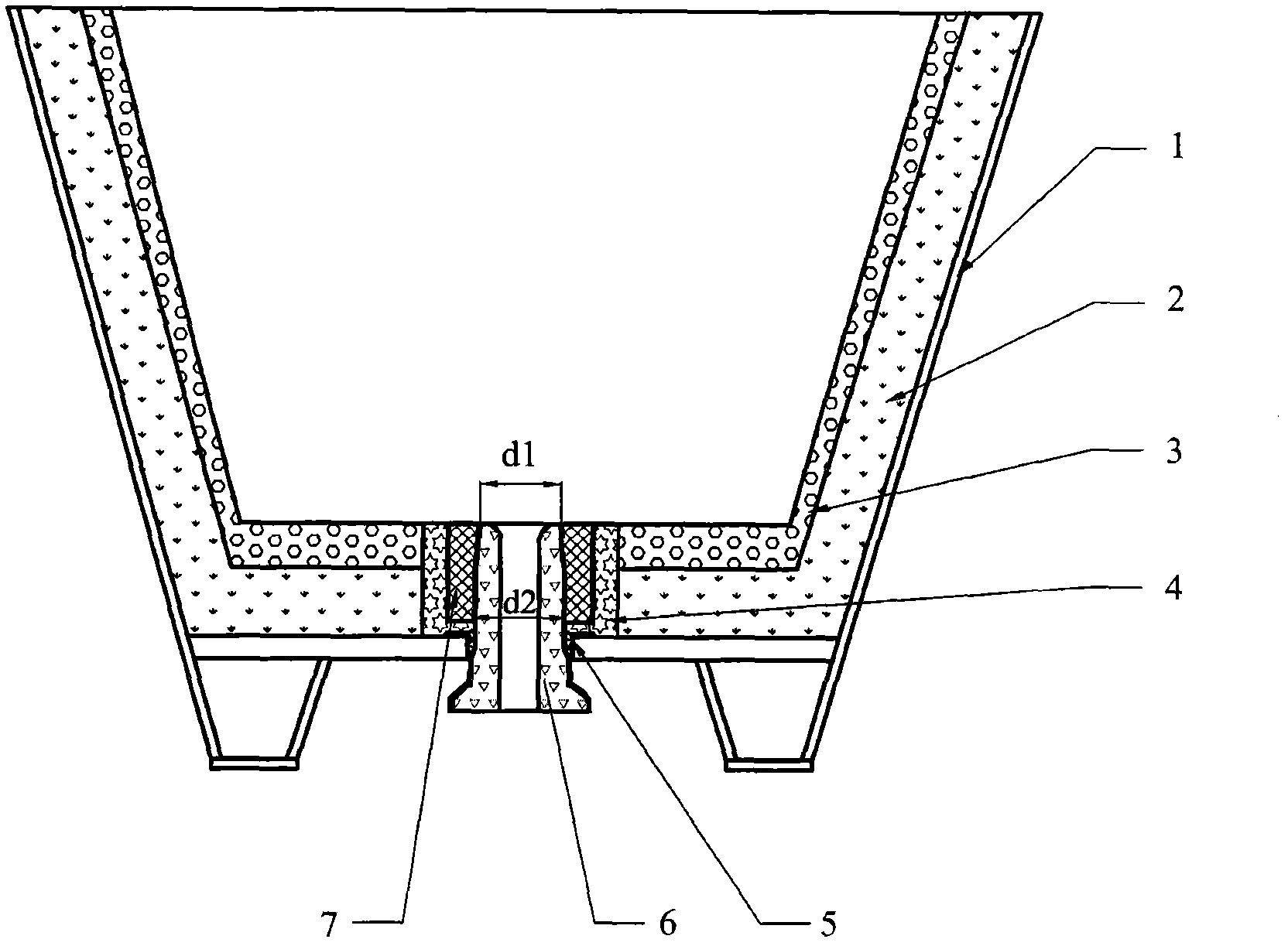
[0042] In this embodiment, the continuous casting tundish includes a cladding 1 , a permanent lining 2 , a working lining 3 , an aluminum carbide silicon carbide ramming material 4 , a sealing ring 5 , an upper nozzle 6 , and a nozzle block 7 . The cladding 1 , the permanent liner 2 and the working liner 3 are formed as a bucket-type or cup-type container without a lid, and the bottom of the container is provided with an opening for letting the molten metal flow out. The permanent lining 2 is formed between the casing 1 and the working lining 3 and is in close contact with the casing 1 and the working lining 3 . During the casting process, the working lining 3 is in direct contact with the molten steel.
[0043] The nozzle seat brick 7 is located in the bottom opening of the permanent lining 2 and the working lining 3, and the upper nozzle 6 is installed in the upper nozzle installation hole 9 of the nozzle seat brick 7.
[0044] The refractory sealing ring 5 fits on the uppe...
Embodiment 2
[0057] The differences between this embodiment and Embodiment 1 are:
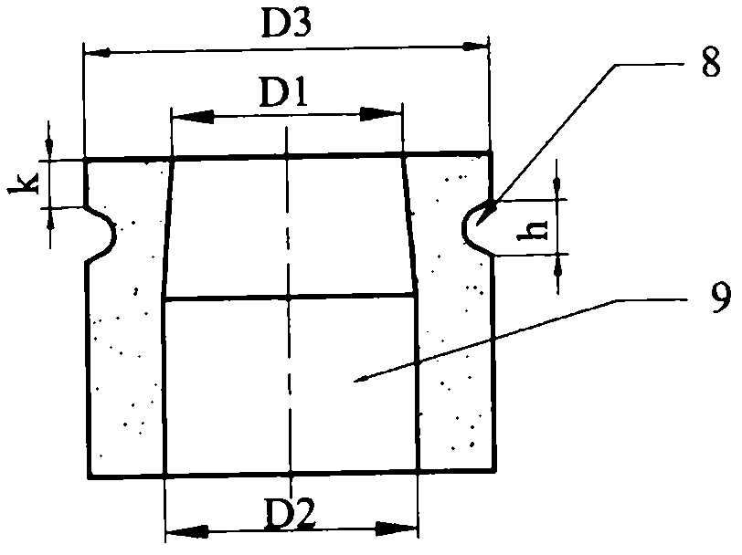
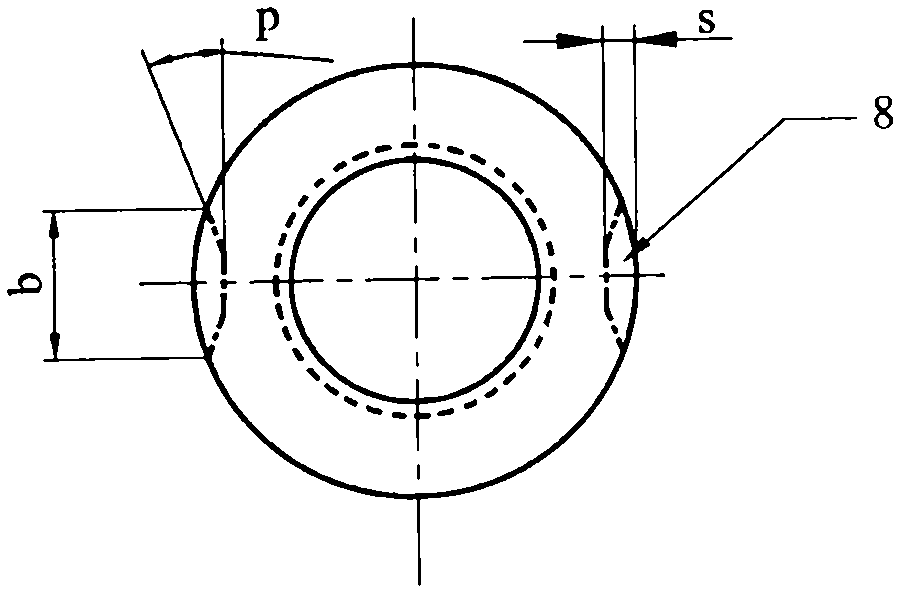
[0058] In the continuous casting tundish of this embodiment, the nozzle block 7 is in the shape of a truncated cone; the diameter D1 of the upper nozzle installation hole 9 is 2.4 mm larger than the outer diameter d1 of the steel connection port of the upper nozzle 6, that is, the upper part of the nozzle block 7 The width of the installation mud joint is 1.2mm; the diameter D2 of the upper nozzle installation hole 9 is 3.0mm larger than the outer diameter d2 of the middle part of the upper nozzle 6, that is, the width of the installation mud joint at the bottom of the nozzle block 7 is 1.5mm; the groove The distance k between the gripper 9 and the top of the outer wall of the nozzle block 7 is 40mm; the height of the groove gripper 8 is h40mm, the width b is 120mm, the depth s is 30mm, and the radian of the inclination p is 45 degrees; the nozzle block 7 contains 98% Al by weight 2 o 3 , the refractorine...
PUM
| Property | Measurement | Unit |
|---|---|---|
| flame retardant | aaaaa | aaaaa |
| density | aaaaa | aaaaa |
| compressive strength | aaaaa | aaaaa |
Abstract
Description
Claims
Application Information
 - R&D
- Intellectual Property
- Life Sciences
- Materials
- Tech Scout
- Unparalleled Data Quality
- Higher Quality Content
- 60% Fewer Hallucinations
Browse by: Latest US Patents, China's latest patents, Technical Efficacy Thesaurus, Application Domain, Technology Topic, Popular Technical Reports.
© 2025 PatSnap. All rights reserved.Legal|Privacy policy|Modern Slavery Act Transparency Statement|Sitemap|About US| Contact US: help@patsnap.com


